Rotary tiller transmission case

A technology of rotary tiller and transmission box, which is applied in the field of soil tillage machinery, and can solve problems such as shallow soil tillage depth, small reaction force, and difficulty in reaching the tillage depth required for planting.

Inactive Publication Date: 2019-06-21
重庆轩通机电有限公司
View PDF0 Cites 0 Cited by
  • Summary
  • Abstract
  • Description
  • Claims
  • Application Information

AI Technical Summary

Problems solved by technology

[0002] In the prior art, rotary tillage mainly uses the rotation of the tool to cut the land to complete related operations. In mountainous and hilly areas, small gasoline engines or small diesel engines are usually used as a series of walking-type agricultural farming machinery powered by small gasoline engines. This kind of small rotary tiller generally does not have a special traction mechanism. When working, it uses the reaction force generated by the rotation of the tool to cut the soil as the traction force to move forward, while the rotary tiller usually uses a small gasoline engine or diesel engine as power and through the transmission. After the box decelerates and increases the torque, it drives the rotary tiller to work. The existing rotary tiller is usually installed on the rotary tiller along the horizontal direction and its axis is set horizontally along

Method used


Image

  • Rotary tiller transmission case
  • Rotary tiller transmission case
  • Rotary tiller transmission case

Examples


Embodiment Construction

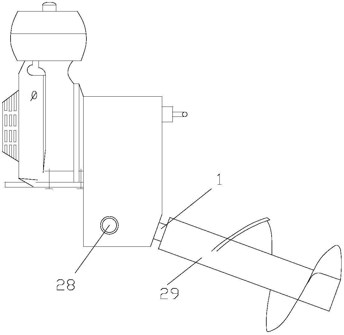
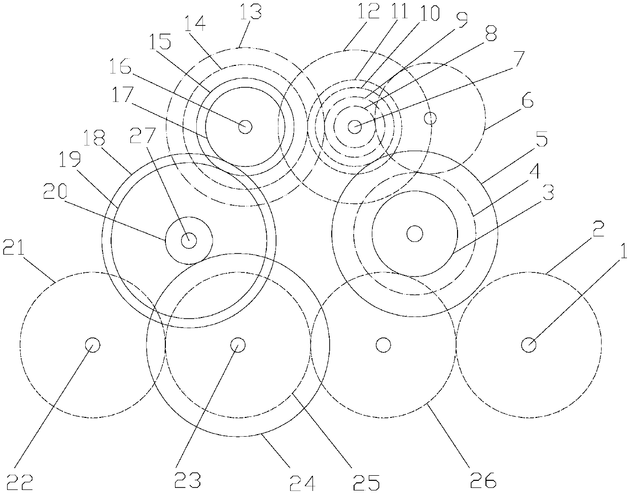
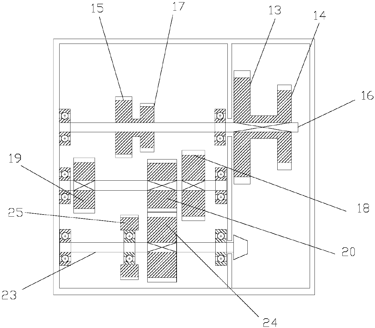
[0022] figure 1 It is a structural schematic diagram of the present invention; figure 2 It is a schematic diagram of the layout of the transmission wheel train of the transmission box of the present invention; image 3 It is a schematic diagram of gear shift transmission of the transmission box of the present invention; Figure 4 It is a schematic diagram of forward rotation transmission of the transmission box of the present invention; Figure 5 It is a schematic diagram of reverse transmission of the transmission box of the present invention; Figure 6 It is a schematic diagram of the arrangement of the cutter drive shaft of the present invention; as shown in the figure, the rotary cultivator transmission box of this embodiment includes the power input shaft 7 and the cutter drive that receives the power of the power input shaft 7 and is used to drive the rotary cultivator 29 to rotate. Shaft 1; the axis of the tool drive shaft 1 is inclined downward so that it forms an ...


PUM


Abstract

The invention discloses a rotary tiller transmission case. The case comprises a power input shaft and a cutter drive shaft for receiving power of the power input shaft and driving the rotation of a rotary cutter. The cutter drive shaft is inclined downward, so that the axis and a horizontal direction form an angle. The rotary tiller transmission case can be applied to a rotary tiller of a cutter tilting type. The reaction force in the axial direction of the cutter during the soil cutting process can be effectively avoided by the tilted rotary cutter. Deep depression of the rotary tiller is effectively avoided during tillage in muddy or deep paddy fields, and the depth of soil tillage is increased due to the downward tilting of the rotary cutter.

Description

technical field [0001] The invention relates to the field of soil tillage machinery, in particular to a rotary tiller transmission box. Background technique [0002] In the prior art, rotary tillage mainly uses the rotation of the tool to cut the land to complete related operations. In mountainous and hilly areas, small gasoline engines or small diesel engines are usually used as a series of walking-type agricultural farming machinery powered by small gasoline engines. This kind of small rotary tiller generally does not have a special traction mechanism. When working, it uses the reaction force generated by the rotation of the tool to cut the soil as the traction force to move forward, while the rotary tiller usually uses a small gasoline engine or diesel engine as power and through the transmission. After the box decelerates and increases the torque, it drives the rotary tiller to work. The existing rotary tiller is usually installed on the rotary tiller along the horizonta...

Claims


Application Information

Patent Timeline
IPC IPC(8): A01B33/08
Inventor 周伟
Owner 重庆轩通机电有限公司
Why Eureka
Try Eureka