Polishing device applicable to shaft parts of different lengths and using method of polishing device

A technology for shaft parts and equipment, which is applied in the field of polishing equipment for shaft parts, can solve problems such as complex workstation transfer steps and complex control procedures, and achieve the effects of easy use, reliable operation, and accelerated polishing speed

Pending Publication Date: 2016-07-27
PUJIANG XIONGDA MACHINERY EQUIP
View PDF5 Cites 11 Cited by
  • Summary
  • Abstract
  • Description
  • Claims
  • Application Information

AI Technical Summary

Problems solved by technology

Especially in the case of manual polishing, this polishing process that varies with different workpieces often involves more complicated and numerous polishing equipment workstations
This creates a negative factor in production costs and involves more complicated station transfer steps or more complicated control procedures

Method used


Image

  • Polishing device applicable to shaft parts of different lengths and using method of polishing device
  • Polishing device applicable to shaft parts of different lengths and using method of polishing device
  • Polishing device applicable to shaft parts of different lengths and using method of polishing device

Examples


Embodiment Construction

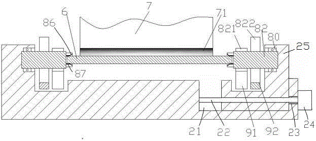
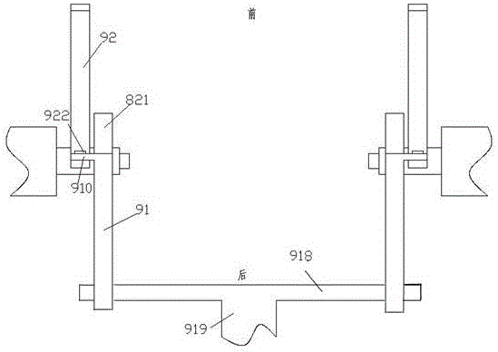
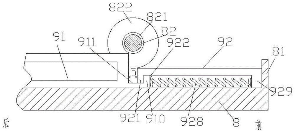
[0010] Combine below Figure 1-3 The present invention will be described in detail.

[0011] A polishing device for a shaft part 6 according to an embodiment includes a polishing part 7 with a polishing bar 71 and a support base 8, and a sliding groove 21 is provided at the right end, and a sliding seat 25 is slidably installed in the sliding groove 21 A drive screw 22 is threadedly installed in the slide seat 25, the left end of the drive screw 22 is rotatably mounted on the left side wall of the slide groove 21, and the right end passes through the right side wall of the slide groove 21 The light hole 23 on the top is connected with the power adjustment motor 24 installed on the outer end of the right side wall of the sliding groove 21, and the left end of the support base 8 and the sliding seat 25 are rotatably supported by bearings 80 There is a clamping driving part 82, and the two clamping driving parts 82 are arranged oppositely so as to clamp the two ends of the shaft...


PUM


Abstract

The invention relates to a polishing device applicable to shaft parts of different lengths and a using method of polishing device. The polishing device comprises a polishing component with a polishing strip and a supporting base. A sliding groove is formed in the right end of the supporting base. A sliding seat is mounted in the sliding groove in a slideable manner. A drive screw is mounted in the sliding seat in a threaded fit manner. The left end of the drive screw is rotatablely mounted on the left side wall of the sliding groove. The right end of the drive screw penetrates through an unthreaded hole in the right side wall of the sliding groove, and is in power connection with a regulating motor mounted at the outer end of the right side wall of the sliding groove. Clamping and driving components are rotatablely supported at the left end of the supporting base and on the sliding seat by virtue of bearings. A gearwheel and a pinion are fixedly mounted on the circumferential surface of each clamping and driving component. The gearwheels are positioned on the outer sides of the clamping and driving components, and the pinions are positioned on the inner sides of the clamping and driving components. The gearwheels and the pinions are used for being meshed with outer racks and inner racks respectively so as to drive the shaft parts to push against the polishing strip and rotate relative to the polishing strip to be polished.

Description

technical field [0001] The invention relates to the field of polishing, in particular to a polishing device that can be used for shaft parts of different lengths and a method for using the same. Background technique [0002] Where the dimensional accuracy of shaft parts is required to be high, polishing and grinding are often required. In order to achieve the required size, size processing and surface finish processing can be performed at the same time as grinding and polishing. This often requires the use of different polishing forces and spin speeds. In order to perform different polishing strategies according to different workpieces, it is often necessary to perform different polishing processes according to different workpiece conditions. Especially in the case of manual polishing, this polishing process that varies with different workpieces often involves relatively complicated and numerous polishing equipment workstations. This creates a disadvantage in terms of pro...

Claims


Application Information

Patent Timeline
Patent Type & Authority Applications(China)
IPC IPC(8): B24B29/04B24B47/12B24B41/06
CPCB24B29/04B24B41/061B24B47/12
Inventor 钟意
Owner PUJIANG XIONGDA MACHINERY EQUIP
Why Eureka
Try Eureka