Supercharge Your Innovation With Domain-Expert AI Agents!

Permanent magnetic suspension high-speed rail

A magnetic levitation, high-speed rail technology, applied in electric traction, electric vehicles, transportation and packaging, etc., can solve the problems of burning out the circuit, expensive, complicated electromagnetic suspension, etc., to solve the problem of wear and tear, the permanent magnet suspension is simple, and the effect of long-term stable suspension

Inactive Publication Date: 2016-07-27
苏伟
View PDF8 Cites 2 Cited by
  • Summary
  • Abstract
  • Description
  • Claims
  • Application Information

AI Technical Summary

Problems solved by technology

Using current to generate a magnetic field will inevitably generate heat. Over time, the circuit will be burned out. To solve the problem, a cooling device is required to make the electromagnetic levitation complicated and expensive.

Method used


Image

  • Permanent magnetic suspension high-speed rail
  • Permanent magnetic suspension high-speed rail

Examples


Embodiment 1

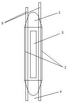
[0026] A new permanent magnetic levitation high-speed rail, which includes:

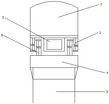
[0027] Suspended car body; NdFeB permanent magnet for suspended car body; power coil; bridge subgrade; bridge pier; permanent magnet track on the bridge,

[0028] NdFeB permanent magnets are embedded in the permanent magnetic guide rail to form a permanent magnetic levitation track. The magnetic poles are as follows: figure 2 As shown, the high-speed rail can be suspended at a high altitude, so that the train can be completely detached from the track and run in suspension.

[0029] When two permanent magnets are facing each other with the same sex, they repel each other in the range of h1, and attract each other in the range of h2. It does not conform to the same-sex repulsion of Coulomb's law, and the magnitude of the force is not inversely proportional to the square of the distance. When two permanent magnets of the same sex are obliquely facing each other, they repel each other within the range ...

Embodiment 2

[0030] The repulsive force experimental data of two permanent magnets of embodiment 2:

[0031] Experiment 1:

[0032] Experimental material: NdFeB N35, size 50×10×5, weight 18g

[0033] Distance mm Repulsion force g

[0034] 12900

[0035] 111050

[0036] 101200

[0037] 91400

[0038] 81650

[0039] 72050

[0040] 62600

[0041] 52900

[0042] Experiment 2:

[0043] Experimental material: NdFeB N35, size 30×5×2, weight 2g

[0044] Distance mm Repulsion force g

[0045] 8185

[0046] 7235

[0047] 6285

[0048] 5385

[0049] 4485

[0050] 3685

[0051] 2985

[0052] Experiment 3:

[0053] Experimental material: NdFeB N35, size 42×6×3, weight 5g

[0054] Distance mm Repulsion force g

[0055] 10300

[0056] 9400

[0057] 8500

[0058] 7600

[0059] 6750

[0060] 5950

[0061] 41300

[0062] 31900

[0063] 22100

[0064] Experiment 4:

[0065] Repulsion force data of two ferrite permanent magnets

[0066] Φ75×Φ32×15

[0067] distance mm repulsion ...


PUM


Abstract

The invention discloses a novel permanent magnetic suspension high-speed rail which comprises a suspended train body, suspended train body permanent magnets, a power coil, a bridge roadbed, piers and permanent magnet tracks on a bridge.A permanent-magnet technology is utilized, wear and a high temperature are not caused to the high-speed rail, and thus the service life is prolonged.The two permanent magnets are repulsive to each other within the range of h1 and attractive to each other within the range of h2 when the two permanent magnets are of the same polarity and repulsive to each other; the situation is not consistent with repulsion of the same polarity of the coulombs law, and the magnitude of action force is not inversely proportional to distance.The two permanent magnets of the same polarity are repulsive to each other within the range of h1 when being opposite to each other in an inclined mode, at the moment, repulsive force exists not only in the vertical direction, in addition, force occurs in the horizontal direction, and the force exists only within the width of the permanent magnets just like Lorentz force and is side thrust.The side thrust is utilized, attractive force within the range of h2 is avoided, and permanent magnetic suspension can be combined.

Description

technical field [0001] The invention belongs to the field of high-speed rail manufacturing, and in particular relates to a permanent magnetic levitation high-speed rail. Background technique [0002] Modern magnetic levitation technology mainly refers to electromagnetic levitation technology, which uses current to generate a magnetic field on the basis of Coulomb's law, and levitates objects through the repulsion or attraction of multiple points. Using current to generate a magnetic field will inevitably generate heat. Over time, the circuit will be burned out. To solve the problem, a cooling device is necessary to make the electromagnetic levitation complicated and expensive. There is another way to levitate objects, that is, permanent magnetic levitation, which makes objects levitate through the mutual repulsion or attraction of permanent magnets. It is simple and cheap, does not consume energy and is environmentally friendly. The permanent magnetic levitation is denied....

Claims


Application Information

Patent Timeline
IPC IPC(8): B60L13/04
CPCB60L13/04
Inventor 苏伟
Owner 苏伟
Features
  • R&D
  • Intellectual Property
  • Life Sciences
  • Materials
  • Tech Scout
  • Unparalleled Data Quality
  • Higher Quality Content
  • 60% Fewer Hallucinations
Learn More