Optical phase put-off precision measurement method and system thereof

A precision measurement, optical phase technology, applied in the field of optical measurement, can solve the problems of low measurement accuracy, high installation and adjustment requirements, complex structure, etc.

Inactive Publication Date: 2008-05-21
大恒新纪元科技股份有限公司北京光电技术研究所
View PDF0 Cites 26 Cited by
  • Summary
  • Abstract
  • Description
  • Claims
  • Application Information

AI Technical Summary

Problems solved by technology

[0007] 1. They are all indirect measurement methods. First measure the rotation angle of the compensation device when the extreme point appears, and then convert it into related phase information. The measurement error is large, the mechanism is complicated, and the instrument cost is high;
[0008] 2. The measurement results are greatly affected by the installation and adjustment errors of the instrument such as collimation and coaxiality;
[0009] 3. When measurin

Method used


Image

  • Optical phase put-off precision measurement method and system thereof
  • Optical phase put-off precision measurement method and system thereof
  • Optical phase put-off precision measurement method and system thereof

Examples


Embodiment Construction

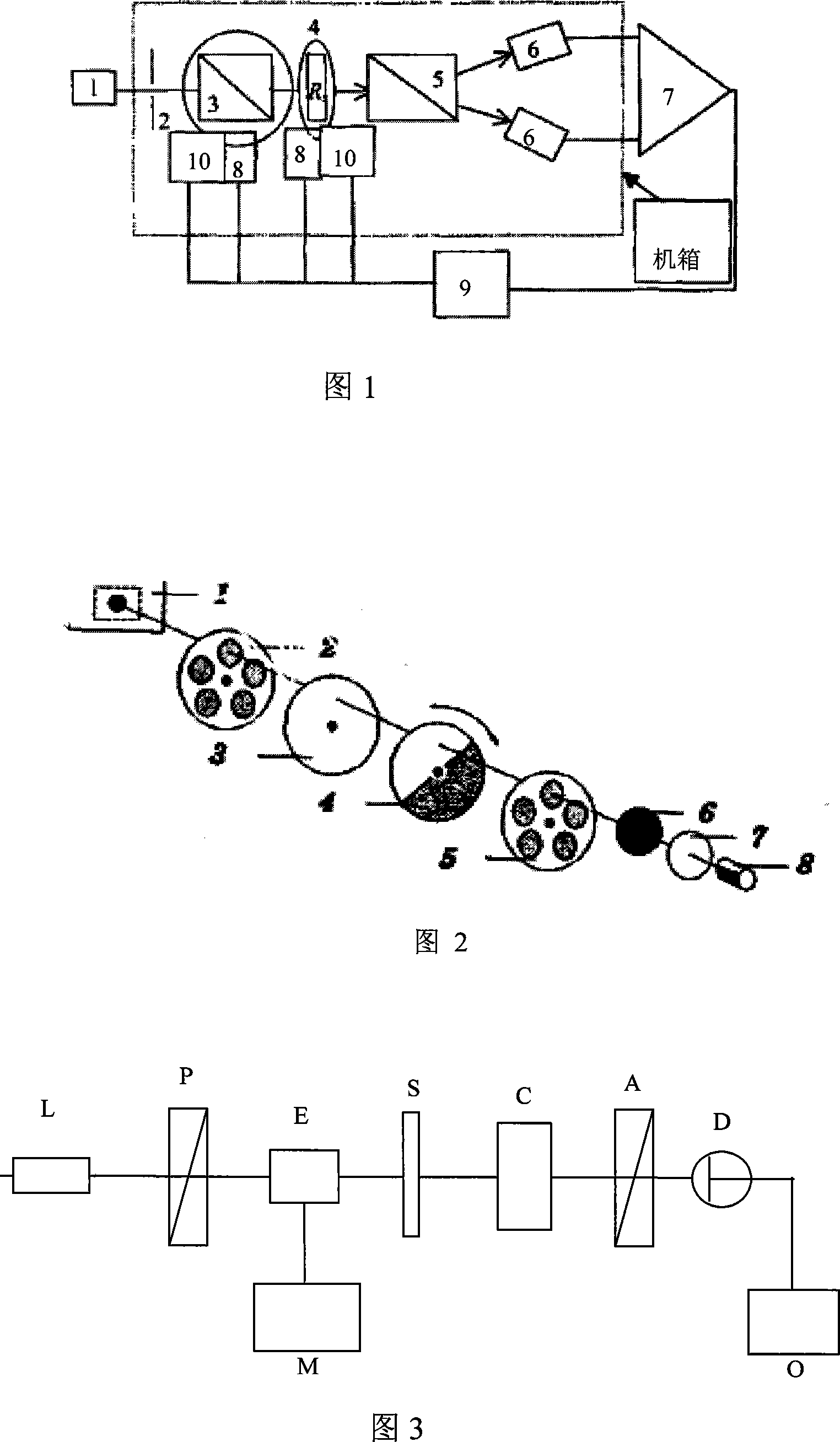
[0056] Specific embodiments of the present invention will now be described in conjunction with the accompanying drawings. The device used in Figure 3 is: the laser L can be a He-Ne laser with a wavelength of 632.8nm and a power of 2mw. Polarizer P and analyzer A can use extinction ratio of 10 5 , Glan-Taylor polarizing prism with aperture>10mm. The optical modulator E can use the KD*P crystal longitudinal modulation method as the modulator. The modulation signal is a sinusoidal voltage, the voltage adjustment range is: 600-2000V, and the modulation frequency is: 2kHz. The Soleil compensator C can be made of quartz material, the working wavelength range is 200-2000nm, the horizontal movement range of the optical wedge is 0-30mm, the movement accuracy is 1μm, and the optical aperture is above 10mm. The light detector D can use a photodiode for photoelectric conversion and detection. A matching signal processing circuit is designed according to the modulation frequency, and t...


PUM


Abstract

The invention discloses an optical phase delay precision measuring method and a system thereof. The system of the invention comprises a laser, a polarizer, a photo-modulator, a modulation signal source, a measuring phase retarder, a phase compensator, a polarization analyzer, an optical detector and a result output unit. The method of the invention is as follows that the optical modulator is added into a light path for optical modulation of detection polarized light and then modulation polarized light is generated; a result display unit realizes conversion from measurement of direct current zero point to measurement of alternate current zero point after conducting filtering process of the received signal, therefore, the position of an extreme point can be determined accurately and the measuring precision can be improved. The measurement of the invention is simple and convenient and the result is accurate and reliable, meanwhile, the precision is up to lambada/300; the invention is suitable for production of a wave plate and other optical delay devices and detection of the product in the sales department.

Description

technical field [0001] The invention relates to an optical phase delay precision measurement method and system thereof, in particular to an optical phase delay precision measurement method and system suitable for measuring optical delay devices such as wave plates, and belongs to the technical field of optical measurement. Background technique [0002] Due to the continuous improvement of industrial production technology, people have put forward higher and higher requirements for the accuracy of devices. Optical instruments have been widely used for their high precision, and more and more attention has been paid to the precision measurement of optical devices. In terms of phase delay measurement of optical devices, the existing precision measurement system adopts beam splitting differential automatic measurement of wave plate phase delay (Hao Dianzhong, Song Lianke, Automatic beam splitting differential measurement of wave plate phase delay, Optoelectronics. Laser , 16(5), 2...

Claims


Application Information

Patent Timeline
IPC IPC(8): G01M11/02
Inventor 宋菲君范玲俞蕾韩永刚林海晏宋建力姚思一
Owner 大恒新纪元科技股份有限公司北京光电技术研究所
Why Eureka
Try Eureka