Method for measuring phase delay devices with different wavelengths

A phase retarder and phase delay technology, applied in the field of optical measurement, to improve the accuracy of measurement, eliminate unstable measurement results, and high signal-to-noise ratio.

Inactive Publication Date: 2011-04-06
大恒新纪元科技股份有限公司北京光电技术研究所
View PDF0 Cites 0 Cited by
  • Summary
  • Abstract
  • Description
  • Claims
  • Application Information

AI Technical Summary

Problems solved by technology

[0004]1. When using the beam splitting differential measurement method, it is necessary to measure the rotation angle of the compensation device when the extreme point appears, and then convert it into relevant phase information. The measurement error is large, and the mechanism Complex and high instrument cost;
[0005]2. When using the light intensity method, such as the beam splitting differential automatic measurement system of wave plate phase delay, directly measure the DC dark spot without modulation Light intensity, since the absolute value of the light intensity is measured, the fluctuation of the light source and the influence of the background light have a great influence on the measurement result, and the measurement accuracy is low;
[0007]4. When the modulation method is used for measurement, if the precision measurement system of the above-mentioned wave plate phase delay is added with a rotatable mechanical-optical rotation modulator, the structure is complex and difficult to install and adjust. High requirements and large errors
[0008]5. The measurement results of most methods are greatly affected by the installation and adjustment errors such as instrument alignment and coaxiality;
[0009]6. Most of the methods are not suitable for multi-wavelength measurement or achromatic wave plate measurement because the basic parameters of the device are related to wavelength

Method used


Image

  • Method for measuring phase delay devices with different wavelengths
  • Method for measuring phase delay devices with different wavelengths
  • Method for measuring phase delay devices with different wavelengths

Examples


Embodiment Construction

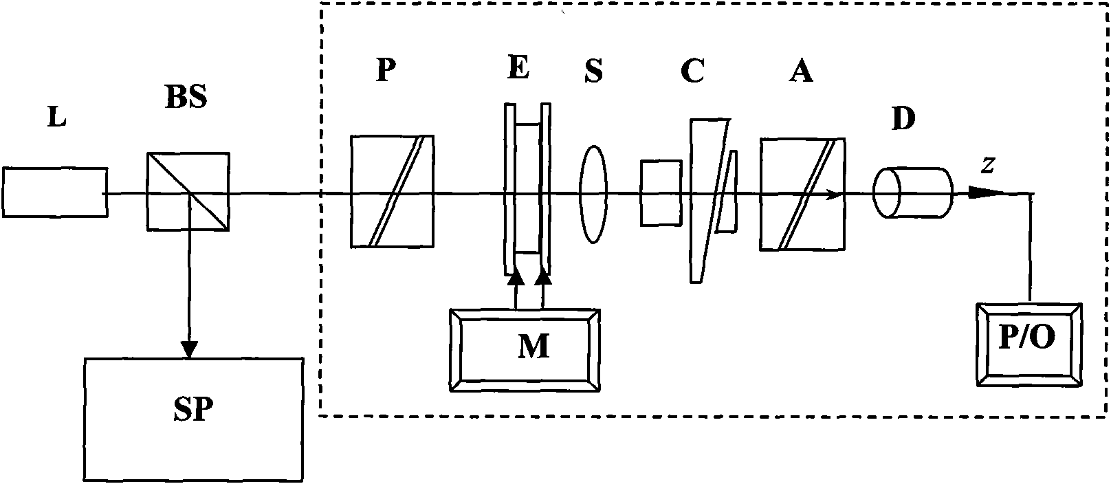
[0048] figure 1 It is a schematic diagram of the present invention. The system includes a laser L, an optical beam splitter BS, a laser monochromator SP, a polarizing prism P, an optical modulator E, a modulation signal source M, a phase retarder S to be measured, a Soleil compensator C, and a polarization analyzer Prism A, photodetector D, signal processing circuit and result output unit P / O. The light emitted by the laser along the z-axis direction is divided into two beams by the beam splitter, one beam is sent to the laser monochromator to measure the spectral value of the laser, and the other beam passes through the polarizing prism, optical modulator, phase retarder to be measured, After the Soleil phase compensator, the analyzer prism, the light detector and the signal processing circuit, the output result is displayed by the result output unit, and the modulation signal source is connected to the light modulator through a signal line.

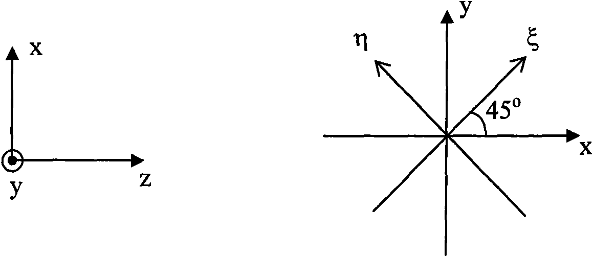
[0049] The azimuth coordinate...


PUM


Abstract

The invention discloses a method for measuring phase delay devices with different wavelengths by a single wavelength light source and a system thereof, which belong to the technical field of optical measurement. A laser light source of the system is spilt into two beams, one beam orderly passes through a polarizer, an optical modulator, a phase retarder to be tested, a phase compensator, an analyzer, and a photodetector, and then a result display unit is used for displaying an output result; and the other beam is output to a laser monochromator. The method comprises the steps of: measuring displacements of the phase compensator corresponding to a group of light sources with different wavelengths respectively first after the establishment of the system; then establishing a fitting curve according to measured data; adding the phase retarder to be tested into a light path, then selecting a laser light source with any wavelength, adjusting the phase compensator, and recording a compensated distance delta L; and finally calculating the phase retardation quantity delta S of the phase retarder to be tested according to the fitting curve and the compensated distance delta L. The method and the system thereof can perform direct measurement on a phase retarder with any central wavelength to be tested, has high measurement accuracy and simple operation, and is easy to commercialize.

Description

technical field [0001] The invention relates to a method for measuring phase delay devices of different wavelengths, in particular to a method for measuring phase delay devices of different wavelengths by using a single wavelength light source, and belongs to the technical field of optical measurement. Background technique [0002] The phase delay is an important parameter of the phase delay device, and its measurement accuracy directly affects the quality of the application system, and with the development of technology and the deepening of research, people put forward higher requirements for the processing and measurement accuracy of the wave plate , for example, the polarization measurement accuracy of the Space Solar Telescope (SST) has been required to reach 10 -4 above. Therefore, improving the measurement accuracy of the phase delay is of great significance for the design and development of high-precision phase delay devices and systems. At present, there are many ...

Claims


Application Information

Patent Timeline
Patent Type & Authority Patents(China)
IPC IPC(8): G01J9/00
Inventor 宋菲君张颖
Owner 大恒新纪元科技股份有限公司北京光电技术研究所
Why Eureka
Try Eureka