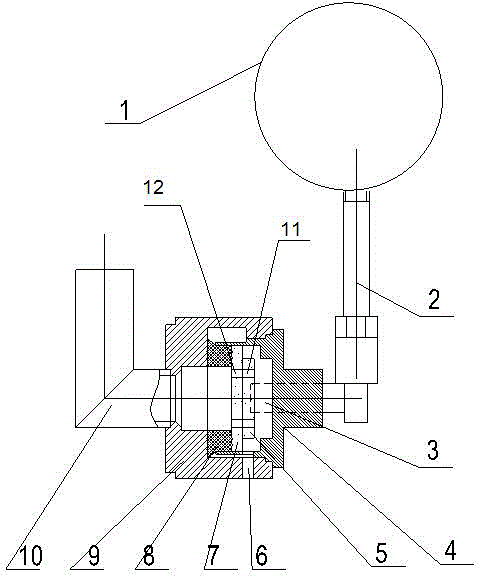
A ceramic sheet type floater switch valve used in an oil storage tank dehydrator
A float switch and dehydrator technology, which can be used in containers, large containers, packaging, etc., can solve the problems of too large floating balls and easy aging of rubber sealing rings, improve reliability and service life, reduce volume, and reduce operating force. small effect
- Summary
- Abstract
- Description
- Claims
- Application Information
AI Technical Summary
Problems solved by technology
Method used
Image
Examples
Embodiment 1
[0016] Such as figure 1 The shown ceramic float switch valve used in the dehydrator of the oil storage tank includes a valve seat 9, a valve housing 4, and a floating ball 1. The water inlet pipe 10 is connected, the valve casing 4 is buckled on one side of the valve seat 9, the floating ball 1 is connected with a connecting rod 2, and the connecting rod 2 is connected with a rotating core 3 perpendicular to it, so The other end of the rotating core 3 passes through the valve casing 4 and goes deep into the valve seat 9, and is fixedly connected with the moving valve plate 5 in the valve seat 9. The valve seat 9 is provided with a static valve for blocking the water inlet pipe 10. Valve sheet 7, the moving valve sheet 5 is closely attached to the static valve sheet 7, and the moving valve sheet 5 is provided with a water outlet hole 11, and the static valve sheet 7 is provided with a water outlet hole 11 conduction The water inlet hole 12, the valve seat 9 is also provided wi...
Embodiment 2
[0018] On the basis of Embodiment 1, it includes valve seat 9, valve housing 4, and float 1. The valve seat 9 is provided with a water inlet pipe 10 communicating with the inside of the valve seat 9, and the valve housing 4 is buckled. On one side of the valve seat 9, the floating ball 1 is connected with a connecting rod 2, and the connecting rod 2 is connected with a rotating core 3 perpendicular to it, and the other end of the rotating core 3 passes through the valve housing 4 Deep into the valve seat 9, and fixedly connected with the movable valve plate 5 in the valve seat 9, the valve seat 9 is provided with a static valve plate 7 for blocking the water inlet pipe 10, and the static valve plate 7 is connected with the valve A gasket 8 is also provided between the inner surfaces of the seats 9 . The moving valve plate 5 is closely attached to the static valve plate 7, and the moving valve plate 5 is provided with a water outlet hole 11, and the static valve plate 7 is prov...
Embodiment 3
[0020] On the basis of embodiment 1 or 2, the moving valve plate 5 rotates relative to the center of the static valve plate 7, and the moving valve plate 5 rotates relative to the static valve plate 7, and the installation process is simple,
[0021] There are two water outlet holes 11, and they are arranged symmetrically along the center of the moving valve sheet 5, and there are also two water inlet holes 12, and they are arranged symmetrically along the center of the static valve sheet 7. On the static valve plate 7, the center is symmetrically arranged to facilitate the conduction between the water outlet hole 11 and the water inlet hole 12. The moving valve plate 5 and the static valve plate 7 are all made of porcelain valve plates, which solves the problem of aging and prolongs the life of the valve. Service life; when working, if the oil storage tank dehydrator does not enter water through the water inlet pipe 10, the water outlet hole 11 on the moving valve plate 5 and ...
PUM
 Abstract
Description
Claims
Application Information
 - R&D
- Intellectual Property
- Life Sciences
- Materials
- Tech Scout
- Unparalleled Data Quality
- Higher Quality Content
- 60% Fewer Hallucinations
Browse by: Latest US Patents, China's latest patents, Technical Efficacy Thesaurus, Application Domain, Technology Topic, Popular Technical Reports.
© 2025 PatSnap. All rights reserved.Legal|Privacy policy|Modern Slavery Act Transparency Statement|Sitemap|About US| Contact US: help@patsnap.com

