Supercharge Your Innovation With Domain-Expert AI Agents!

Maneuvering type roller way conveying mechanism for conveying

A roller conveying mechanism and motorized technology, applied in the direction of conveyor objects, rollers, rollers, etc., can solve problems such as safety hazards, unsatisfactory, accidents, etc.

Active Publication Date: 2016-07-27
东营市东凯园区运营管理有限公司
View PDF5 Cites 1 Cited by
  • Summary
  • Abstract
  • Description
  • Claims
  • Application Information

AI Technical Summary

Problems solved by technology

However, this kind of roller table device also has potential safety hazards. Due to its passive drive, when the pushing force during transportation is less than the sliding force generated by gravity, the objects are prone to reverse slide and accidents
However, in some devices with rollers that can rotate in one direction, because the rollers are fixed and rotate in one direction, they cannot meet the needs of being applicable to different inclination situations, and they cannot be used for horizontally oriented two-way article transmission.

Method used


Image

  • Maneuvering type roller way conveying mechanism for conveying
  • Maneuvering type roller way conveying mechanism for conveying

Examples


Embodiment Construction

[0008] Combine below Figure 1-2 The present invention will be described in detail.

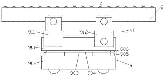
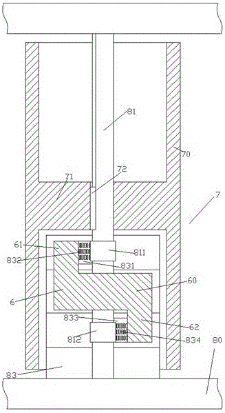
[0009] According to an embodiment of the present invention, the motorized roller conveying mechanism used for conveying includes a mobile cart 9 and a roller device 8 mounted on the motorized cart 9 through a height and inclination adjustment device 91 A series of rollers 7 are installed side by side in the roller table device 8, wherein the rollers 7 include a cylinder wall 70 and an integrally formed support disc 71 located in the axial middle of the cylinder wall 70, so that the support disc 71 The inner space of the cylinder wall 70 is divided into two chambers, the support plate 71 is mounted on the shaft 81 rotatably supported in the side wall 80 of the roller table device 8 through the key 72, wherein, At least one of the two chambers accommodates a fixed support frame 83 protruding from the side wall 80 of the adjacent roller table device 8, and the fixed support frame 83 carries a d...


PUM


Abstract

A maneuvering type roller way conveying mechanism for conveying comprises a maneuvering type carrying trolley (9) convenient to move and a roller way device (8) mounted on the maneuvering type carrying trolley (9) through a height and dip angle adjusting device (91). A series of rollers (7) are mounted in the roller way device (8) side by side. Each roller (7) comprises a barrel wall (70) and an integrally-formed supporting disc (71) located in the axial middle of the barrel wall (70), so that the inner space of the barrel wall (70) is divided by the supporting disc (71) into two chambers, the supporting disc (71) is mounted on a rotary shaft (81) through a key (72), and the rotary shaft (81) can be rotationally supported in a side wall (80) of the roller way device (8).

Description

technical field [0001] The invention relates to the field of conveying devices, in particular to a motorized roller conveying mechanism for conveying. Background technique [0002] Roller conveyors are widely used in conveying items. In some occasions where items need to be transported from a low place to a high place, such as the transport of heavy items, it is necessary to use the roller table device to provide a transition slope to facilitate pushing the items directly to the destination. The rollers of this roller table arrangement are passively driven, rotating rollers. By adjusting the inclination angle of the roller table, it can be applied to assist in conveying articles in various situations. However, this roller table device also has potential safety hazards. Due to its passive drive, when the pushing force during transportation is less than the sliding force generated by gravity, the objects are prone to reverse slide and accidents. And in some devices that are...

Claims


Application Information

Patent Timeline
Patent Type & Authority Applications(China)
IPC IPC(8): B65G13/00B65G13/12B65G39/02
CPCB65G13/00B65G13/12B65G39/02
Inventor 余苏祥
Owner 东营市东凯园区运营管理有限公司
Features
  • R&D
  • Intellectual Property
  • Life Sciences
  • Materials
  • Tech Scout
  • Unparalleled Data Quality
  • Higher Quality Content
  • 60% Fewer Hallucinations
Learn More