
Wear-resistant layer fusion composite technology of scraper conveyor and scraper conveyor with wear-resistant layer

A technology of scraper conveyor and compound process, which is applied in conveyors, manufacturing tools, transportation and packaging, etc., can solve problems affecting production continuity and construction difficulty, failure to achieve good wear resistance, and affecting normal operation of equipment, etc. Achieve the effects of avoiding thermal deformation, reducing component size changes, and reducing cladding costs

Inactive Publication Date: 2018-03-20
过秉坤
View PDF7 Cites 0 Cited by
  • Summary
  • Abstract
  • Description
  • Claims
  • Application Information

AI Technical Summary

Problems solved by technology

[0003] Most of the middle tanks of the existing scraper conveyors are not equipped with wear-resistant layers, resulting in a short service life of the equipment. Since the middle tanks are mostly fixed under the mine, the equipment is bulky and inconvenient to replace, which greatly affects the continuity of production and Difficulty in construction; even if there is a middle groove of the conveyor equipped with a wear-resistant layer, the design of the wear-resistant layer is unreasonable, which affects the normal operation of the equipment. At the same time, the wear-resistant effect is not good, and a good wear-resistant effect cannot be achieved

Method used


Image

  • Wear-resistant layer fusion composite technology of scraper conveyor and scraper conveyor with wear-resistant layer
  • Wear-resistant layer fusion composite technology of scraper conveyor and scraper conveyor with wear-resistant layer
  • Wear-resistant layer fusion composite technology of scraper conveyor and scraper conveyor with wear-resistant layer

Examples


Embodiment Construction

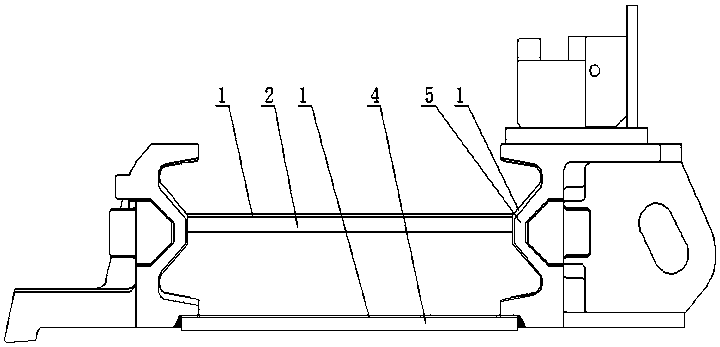
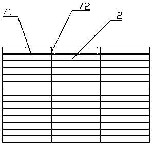
[0042] like figure 1 , figure 2 and image 3 The shown scraper conveyor with a wear-resistant layer is a mature prior art, including a bottom plate 4 , a middle plate 2 and an E-shaped groove 5 . In the present application, on the basis of the prior art, a wear-resistant layer 1 is provided on the bottom plate 4, the middle plate 2 and the E-shaped groove edge 5, and the wear-resistant layer 1 is provided to enhance the wear resistance of the scraper conveyor, so that the scraper Conveyor is more suitable for coal mine transportation.

[0043] Wherein, the setting positions of the wear-resistant layer 1 are the upper surfaces of the bottom plate 4, the middle plate 2 and the E-shaped groove edge 5; the thickness of the wear-resistant layer 1 is 3-5mm, preferably 4mm. The wear resistance of the bottom plate 4, the middle plate 2 and the E-shaped groove 5 is enhanced, and on the other hand, the normal operation of the bottom plate 4, the middle plate 2 and the E-shaped groov...


PUM

PropertyMeasurementUnit
thicknessaaaaaaaaaa
lengthaaaaaaaaaa
lengthaaaaaaaaaa

Abstract

The invention discloses a melting compound process for abrasion-resistant layers of a scraper plate conveyor and the scraper plate conveyor with the abrasion-resistant layers. The scraper plate conveyor comprises a bottom plate, a middle plate and an E-shaped ledge. The bottom plate, the middle plate and the E-shaped ledge are all provided with the abrasion-resistant layers. The melting compound process for the abrasion-resistant layers comprises the steps that firstly, the middle plate is horizontally arranged on the upper face, and the upper surface of the middle plate is pressed by a pressing plate and faces upwards; secondly, welding machine parameters are adjusted; and finally, surfacing is conducted, specifically, the welding machine runs in the width direction of the middle plate and then runs in the length direction of the middle plate, and a continuous melt plated band is formed through sequential cycles. The middle plate, the bottom plate and the E-shaped ledge of the scraper plate conveyor are provided with the abrasion-resistant layers, so that the abrasion resistance of the scraper plate conveyor is improved. Meanwhile, through melting compound of the abrasion-resistant layers, the abrasion-resistant layers subjected to melting compound is even in thickness, low in cost and good in application effect.

Description

technical field [0001] The invention belongs to the field of scraper conveyors, and in particular relates to a scraper conveyor wear-resistant layer melting and compounding process and a scraper conveyor with wear-resistant layers. Background technique [0002] In the production of coal mines, scraper conveyors are used in conjunction with shearers, hydraulic supports and other equipment to transport the coal mines under the fully mechanized mining face to subsequent equipment. The traction mechanism of the scraper conveyor is the scraper chain, the carrying device is the middle groove, and the scraper chain is installed on the groove surface of the middle groove. The middle trough is fully laid along the transportation route, and is matched with the drum shearer and the conveyor pushing device to realize the mechanization of coal falling, coal loading, coal transportation and pushing transportation. The middle groove of the scraper conveyor is subject to various effects su...

Claims


Application Information

Patent Timeline
Patent Type & Authority Patents(China)
IPC IPC(8): B65G19/28B23K9/04
CPCB23K9/042B65G19/28
Inventor 过秉坤赵恒付伟雷恩玉陶宾
Owner 过秉坤
Learn More