
A multi-way valve group with three pumps converging and hydraulic excavator

A technology of hydraulic excavators and multi-way valves, which is applied in the direction of earth movers/shovels, fluid pressure actuators, mechanical equipment, etc., which can solve problems such as slow operation and insufficient oil supply, and achieve increased digging force and improved Excavation efficiency, ensuring the effect of the boom priority function

Active Publication Date: 2017-11-10
SUOTE TRANSMISSION EQUIP
View PDF1 Cites 0 Cited by
  • Summary
  • Abstract
  • Description
  • Claims
  • Application Information

AI Technical Summary

Problems solved by technology

[0004] Aiming at the above-mentioned problems in the prior art, a three-pump combined multi-way valve group and hydraulic multi-way valve are now provided, aiming at solving the problem that the flow provided at the main oil inlet is not enough to maintain the coordinated action between the actuators In order to ensure the coordination of the actions of the various actuators of the compound action and improve the work efficiency

Method used


Image

  • A multi-way valve group with three pumps converging and hydraulic excavator
  • A multi-way valve group with three pumps converging and hydraulic excavator
  • A multi-way valve group with three pumps converging and hydraulic excavator

Examples


Embodiment Construction

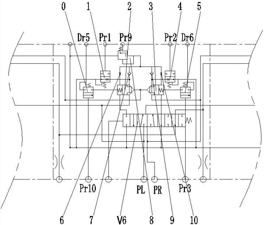
[0035] In order to make it easy to understand the technical means, creative features, goals and effects achieved by the present invention, the following examples are combined with the appended Figures 1 to 6 The multi-way valve group of three-pump confluence provided by the present invention is described in detail.

[0036] figure 1 It is a schematic diagram of the working state of an embodiment of a multi-way valve group with three pumps converging Figure 1 , figure 2 Schematic diagram of the working state of the middle control link of an embodiment of a three-pump confluence multi-way valve group Figure 1 , image 3 It is a schematic diagram of the working state of an embodiment of a multi-way valve group with three pumps converging Figure II , Figure 4 Schematic diagram of the working state of the middle control link of an embodiment of a three-pump confluence multi-way valve group Figure II ,Such as Figure 1 to Figure 4As shown in , the three-pump combined m...


PUM


Abstract

The invention discloses a three-pump confluence multi-way valve block and a hydraulic excavator. The three-pump confluence multi-way valve block comprises an intermediate control joint, a left executing joint and a right executing joint, wherein the left executing joint comprises a left walking control valve, a backup control valve, a bucket control valve, a second control valve of a bucket rod, and a first control valve of a movable arm, which sequentially communicate; the right executing joint comprises a right walking control valve, a rotation control valve, a second control valve of the movable arm, and a first control valve of the bucket rod, which sequentially communicate; the intermediate control joint comprises a linear walking control valve, a first confluence valve and a second confluence valve, two main oil inlets which are separately connected with a main oil pump are formed, auxiliary oil inlets are separately formed in the left executing joint and the right executing joint, and the two auxiliary oil inlets are jointly connected with an auxiliary oil pump. According to the technical scheme adopted by the invention, when flow provided by the two main oil inlets is not sufficient to maintain coordinating motion between executing mechanisms, the auxiliary pump can be opened, oil is supplied to the movable arm through the auxiliary oil inlets, and hydraulic oil provided by the main oil pump can sufficiently coordinate the motion of the remaining executing mechanisms.

Description

technical field [0001] The invention relates to the field of excavators, in particular to a three-pump combined multi-way valve group and a hydraulic excavator. Background technique [0002] Hydraulic excavator is a kind of construction machinery widely used in earthwork construction. As its core control unit, the main control valve group is a hydraulic multi-way control valve with highly integrated functions. The structure and operation mode of the hydraulic multi-way valve determine The control mode and operation performance of the hydraulic system of the excavator are studied. At present, the mainstream hydraulic circuits of large excavators on the market mainly include three types: negative flow control hydraulic system, positive flow control hydraulic system, and load sensitive hydraulic system. After years of market verification, the three types of hydraulic control systems have developed relatively mature. However, the three types of hydraulic control systems are no...

Claims


Application Information

Patent Timeline
Patent Type & Authority Patents(China)
IPC IPC(8): F15B13/02E02F9/22
CPCE02F9/2267F15B13/02
Inventor 于晓晨刘中华陆爱华
Owner SUOTE TRANSMISSION EQUIP
Learn More