Coupling locking device

A technology for locking devices and couplings, applied in the direction of couplings, rigid shaft couplings, mechanical equipment, etc., can solve problems such as disassembly and installation troubles

Inactive Publication Date: 2016-07-27
SHANGHAI LIANCHENG(GRP) CO LTD
View PDF0 Cites 3 Cited by
  • Summary
  • Abstract
  • Description
  • Claims
  • Application Information

AI Technical Summary

Problems solved by technology

Not only that, when the pump needs to be repaired, it als

Method used


Image

  • Coupling locking device
  • Coupling locking device
  • Coupling locking device

Examples


Embodiment Construction

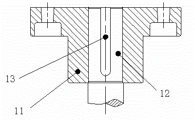
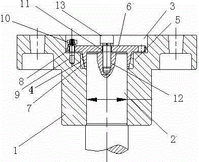
[0006] The coupling 1 and the shaft 2 in the figure are characterized in that: a large counterbore 3 is opened on the upper part of the shaft hole of the coupling, and then a small counterbore 4 is opened on the bottom of the large counterbore, and placed in the small counterbore A small taper sleeve 5, the outer sides of the cross-section of the small taper sleeve are right-angled sides, the slope is on the inside, the bottom is located at the bottom of the small counterbore, the right-angled side is located at the side of the small counterbore, and a large cone is placed in the large counterbore Sleeve 6, the bottom of the large taper sleeve has a convex taper sleeve 7, the inner sides of the cross section of the taper sleeve are right-angled sides, the outer side is a slope, the slope of the taper sleeve convex downward and the small cone The slopes of the cover are attached, and a threaded hole 8 is provided on the outside of the bottom of the large taper sleeve, and a corr...


PUM


Abstract

The invention provides a coupling locking device. The coupling locking device comprises a coupling and a shaft, and is characterized in that a big counter bore is formed in the upper portion of a shaft hole of the coupling; a small counter bore is formed in the bottom face of the big counter bore; a small taper sleeve is placed in the small counter bore; the two edges of the outer side of the cross section of the small taper sleeve are right-angle sides, a bevel is located inside, a base is located on the bottom face of the small counter bore, and a right-angle side edge is located on the side face of the small counter bore; a big taper sleeve is placed in the big counter bore; the bottom of the big taper sleeve is provided with a downward convex taper sleeve, the two edges of the inner side of the cross section of the taper sleeve are right-angle sides, and an outer side edge is a bevel; the bevel of the downward convex taper sleeve of the big taper sleeve is attached to the bevel of the small taper sleeve; the outer side of the bottom of the big taper sleeve is provided with a threaded hole; the bottom face of the big counter bore is provided with a corresponding threaded hole; and a stud is screwed into the two threaded holes. The coupling locking device has the advantages that torque is transmitted without a key, so that a key groove does not need to be milled in the shaft; and accordingly, the strength of the shaft is improved, and the disassembling and assembling of the coupling are facilitated.

Description

technical field [0001] The invention relates to a coupling locking device. Especially elastic pin couplings for pumps. Background technique [0002] The shaft coupling 11 and the shaft 12 in the prior art adopt an interference fit, and the torque is transmitted by the key 13 . When the shaft diameter 6<d≤30, the matching between the coupling and the shaft is H7 / j6; when the shaft diameter is 30<d≤50, the matching between the coupling and the shaft is H7 / k6; when the shaft diameter d>50 When the coupling and the shaft fit H7 / m6. In this way, the workshop will adopt the method of hot loading to assemble, which brings potential danger to the workshop operators. Not only that, when the pump needs to be repaired, it also brings a lot of trouble to disassembly and installation. Contents of the invention [0003] The purpose of the present invention is (1) to change the interference fit into a clearance fit, which is more convenient for installation and disassembly; ...

Claims


Application Information

Patent Timeline
IPC IPC(8): F16D1/076F16D1/09
Inventor 李威王满群张锡淼
Owner SHANGHAI LIANCHENG(GRP) CO LTD
Why Eureka
Try Eureka