Supercharge Your Innovation With Domain-Expert AI Agents!

Petroleum pipeline blocking structure

A technology of oil pipelines and sealing caps, which is applied in the direction of pipe components, pipes/pipe joints/fittings, mechanical equipment, etc., which can solve the problems of poor practicability, inconvenient use, and the blocking structure cannot realize the blocking function, etc., to prolong the service life , Reduce metal fatigue and ensure stable performance

Inactive Publication Date: 2016-07-27
TONGLIANG BAOKE MACHINERY MFG
View PDF0 Cites 0 Cited by
  • Summary
  • Abstract
  • Description
  • Claims
  • Application Information

AI Technical Summary

Problems solved by technology

[0003] The object of the present invention is to provide an oil pipeline plugging structure, which solves the problems of poor practicability and inconvenient use of previous plugging devices
When the oil pipeline is repaired and replaced, it is necessary to seal the nozzle to prevent the residual liquid in the pipe from flowing out and causing waste. In the existing sealing structure, the sealing function can only be realized through complicated operations such as installation, fixing, and advancement, and A single sealing structure for pipelines with different diameters cannot realize its sealing function; the present invention makes further improvements to the prior art, adding a push rod to the hollow hemispherical sealing cover, and utilizing the The ring-shaped enlarged part of the outer eaves, which is sunken inward in the middle, utilizes the good deformation ability of elastic rubber to force the sealing cover to move forward when the push rod is driven, and the enlarged part is deformed by force, that is, the outermost end of the enlarged part faces the seal. The outer circumferential direction of the cover is bent, and through the supporting force and elastic force provided by the elastic metal block embedded in the depression of the enlarged part, the deformation of the enlarged part itself produces a radially outward extrusion force on the inner wall of the pipe, and then the body of the sealing cover is tightened. Tightly fixed on the inner wall of the pipe;

Method used


Image

  • Petroleum pipeline blocking structure
  • Petroleum pipeline blocking structure

Examples


Embodiment 1

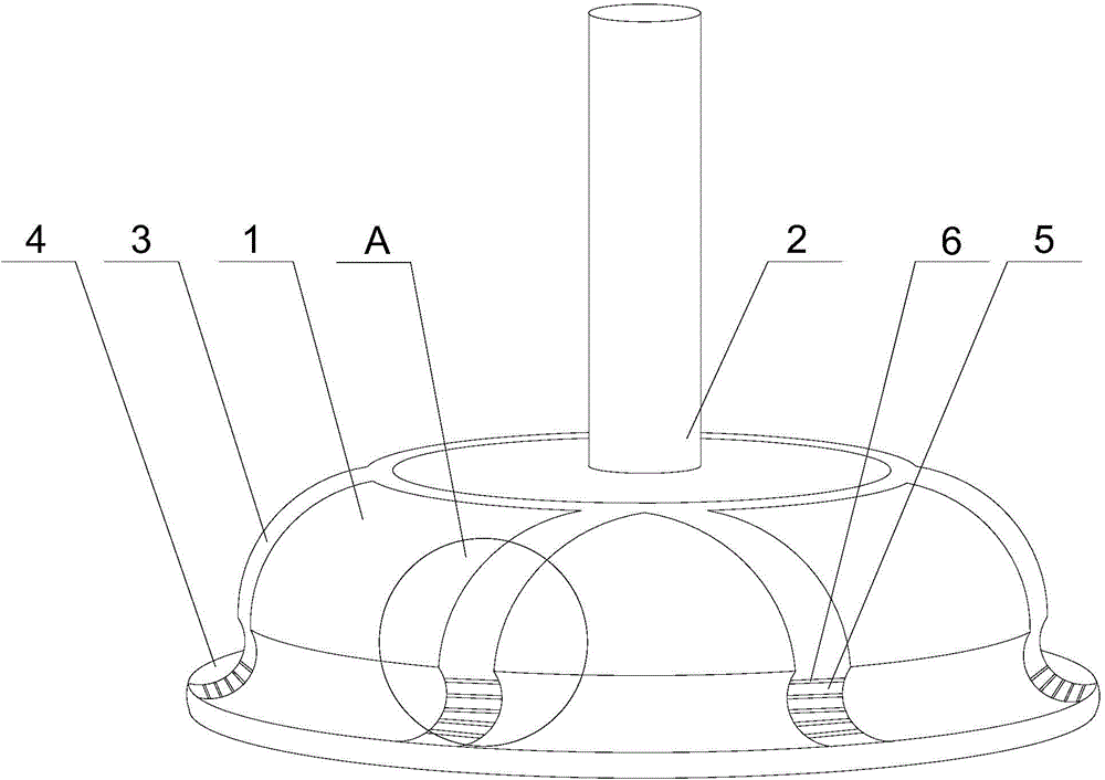
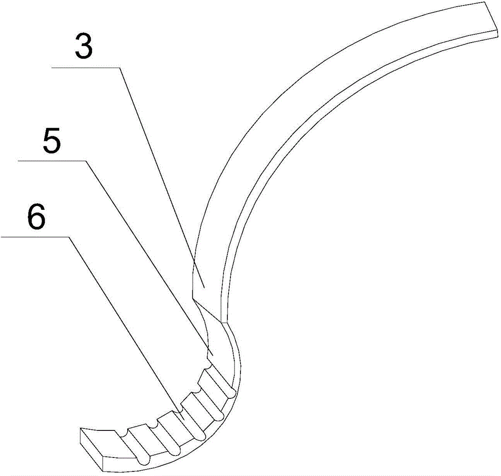
[0020] Such as figure 1 and figure 2 As shown, this embodiment includes a hollow hemispherical sealing cover 1 and a push rod 2 fixed on the bottom of the sealing cover 1. On the outer eaves of the sealing cover 1, an annular enlarged part 4 with the middle part sunken inward is fixed. The enlarged part 4 is elastic rubber, and a plurality of arc-shaped pieces 3 are embedded on the outer wall of the sealing cover 1. The plurality of arc-shaped pieces 3 are radial along the direction from the bottom of the sealing cover 1 to its outer circumference. The end of the arc-shaped piece 3 is connected with an arc-shaped elastic metal block 5, and the elastic metal block 5 is embedded in the depression of the enlarged part 4; a plurality of contraction grooves are opened on the curved inner wall of the elastic metal block 5 6, and a plurality of said shrinkage grooves 6 are parallel to each other.

[0021] The present invention makes further improvements to the prior art. A push ro...


PUM


Abstract

The present invention discloses a petroleum pipeline blocking structure. The petroleum pipeline blocking structure comprises a hollow hemispheric sealing cover and a push rod fixed at the bottom of the sealing cover; an annular expansion portion with the middle inwardly recessed is fixed on an outer edge of the sealing cover; a plurality of arc-shaped pieces are embedded into an outer wall of the sealing cover; the plurality of arc-shaped pieces are radially disposed in directions from the bottom of the sealing cover towards the outer circumference of the sealing cover; and the tail end of each arc-shaped piece is connected with an arc-shaped elastic metal block embedded in the recessed position of the expansion portion. Through self displacement changes of the hollow hemispheric sealing cover, air in a pipeline can be compressed and extruded, so that air pressure of the outside of the sealing cover is slightly greater than that of the inside of the sealing cover, the sealing cover can be fixed on an inner wall of the pipeline more stably, and the problem that a traditional blocking device is poor in practicability and inconvenient to use is solved.

Description

technical field [0001] The invention relates to the field of automobile manufacturing, in particular to an oil pipeline plugging structure. Background technique [0002] The oil tank and the engine are connected by an oil pipeline, but when the engine has equipment failure or needs to be repaired, the oil pipeline needs to be disconnected, that is, the opening and closing of the oil delivery is realized through the switch valve, but due to the existence of A certain distance, and there is still a certain amount of oil in the oil pipeline after the on-off valve is closed. After the oil leaks, it will easily cause pollution to the surrounding environment and cause a large waste; Plugging is carried out to prevent the staff from opening the pipeline without knowing it, causing leakage and affecting the maintenance progress. In the past, matching oil pipe end caps were generally used for sealing when plugging, but due to the poor sealing performance of the end caps, during insta...

Claims


Application Information

Patent Timeline
Patent Type & Authority Applications(China)
IPC IPC(8): F16L55/105
Inventor 谭学彬
Owner TONGLIANG BAOKE MACHINERY MFG
Features
  • R&D
  • Intellectual Property
  • Life Sciences
  • Materials
  • Tech Scout
  • Unparalleled Data Quality
  • Higher Quality Content
  • 60% Fewer Hallucinations
Learn More