Solid-liquid universal type thermal stimulus current measuring device

A thermally stimulated current and measuring device technology, applied in measuring devices, material analysis through electromagnetic means, material thermal analysis, etc., can solve problems such as the accuracy of liquid dielectrics, contamination of measuring devices, and difficult liquid dielectric containment and testing. Achieve the effects of wide temperature range, good electromagnetic shielding performance, and less cooling medium consumption

Active Publication Date: 2016-07-27
TSINGHUA UNIV +3
View PDF6 Cites 11 Cited by
  • Summary
  • Abstract
  • Description
  • Claims
  • Application Information

AI Technical Summary

Benefits of technology

This patented technology allows for accurate measurements on both types of materials at different temperatures without causing excessive evaporation or contamination from other substances that may affect their properties during testing. It also includes an improved method for accurately measuring heat transfer between two samples while maintaining proper pressure control over them. Overall, this technology provides technical benefits such as enabling effective use of thermally activated fluorescent dyes (TDFs) for various applications like biological researches.

Problems solved by technology

This patented technical solution described in the patents relating to thermally induced currenecrosis involves studying the effects of changes made during exposure to certain substances called activated carbon or modified carbons when exposed to specific conditions like voltage change. These modifications can affect the physical characteristics of these compounds, making them more useful for applications that require precise measurements over wide ranges of temperatures and pressures. Current methods have drawbacks including volatile liquids evaporation from the air due to rapid cooling upon annealing with strong magnetic fields, contaminations caused by insulating layers within the sample, difficulty in obtaining consistently reliable results through both static and dynamic tests, and potential interference issues associated with other types of experiments conducted simultaneously.

Method used


Image

  • Solid-liquid universal type thermal stimulus current measuring device
  • Solid-liquid universal type thermal stimulus current measuring device

Examples


Embodiment Construction

[0027] Embodiments of the present invention are described in detail below, examples of which are shown in the drawings, wherein the same or similar reference numerals designate the same or similar elements or elements having the same or similar functions throughout. The embodiments described below by referring to the figures are exemplary only for explaining the present invention and should not be construed as limiting the present invention.

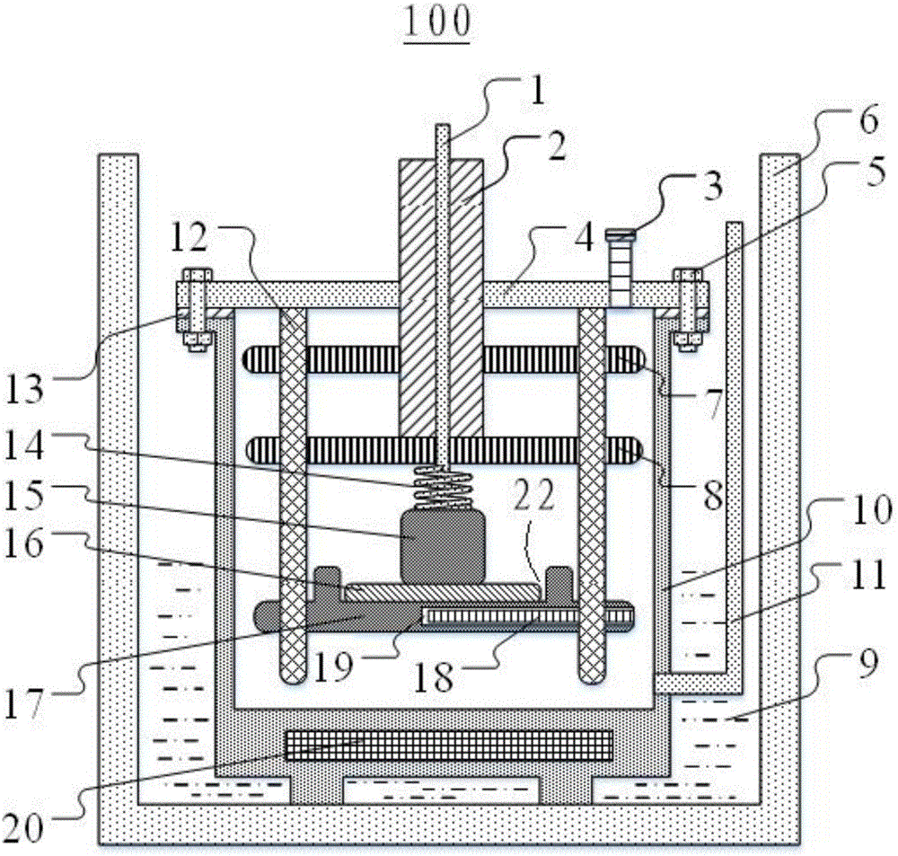
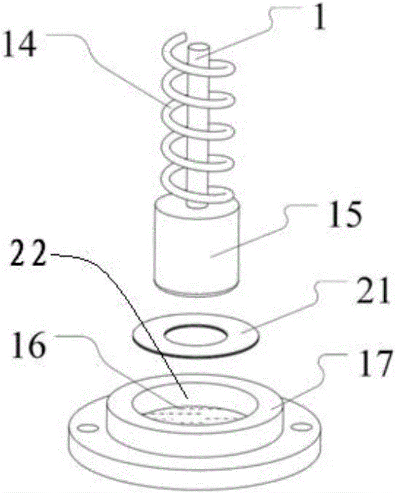
[0028] Combine below figure 1 and figure 2 The solid-liquid universal thermal stimulation current measurement device 100 according to the embodiment of the present invention is described in detail. The solid-liquid general thermal stimulation current measurement device 100 can be used for thermal stimulation current performance testing of dielectric materials. Wherein, the up-down direction and the left-right direction are subject to the up-down direction and the left-right direction when the solid-liquid universal thermal stimulation ...


PUM


Abstract

The invention discloses a solid-liquid universal type thermal stimulus current measuring device. The device comprises a vacuum insulation barrel, fixed pillars, a lower electrode, an insulation sleeve, an upper electrode, a glass ring, an upper partition board, a lower partition board and a spring, wherein a measurement cavity is formed in the vacuum insulation barrel, a top cover is arranged on the top of the measurement cavity to seal the measurement cavity, a heater is arranged on the measurement cavity, a nitrogen inlet is formed in the measurement cavity, an exhaust port is formed in the top cover, and a cooling medium is arranged between the measurement cavity and the vacuum insulation barrel; the upper end of the fixed pillar is connected with the top cover, the lower electrode is connected with the fixed pillars, and the lower electrode is provided with a groove and a temperature sensor; a metal conductive core penetrates through the insulation sleeve, the upper electrode is connected with the metal conductive core and opposite to the lower electrode in the vertical direction, and the glass ring is placed in the groove and can be taken out; the upper partition board and the lower partition board are arranged in a vertically alternating mode and located above the upper electrode, and the spring is arranged on the outer side of the metal conductive core in a sleeving mode and located between the upper electrode and the lower partition board. The device can be used for measurement of both solid dielectric and liquid dielectric.

Description


Claims


Application Information

Patent Timeline
Owner TSINGHUA UNIV
Why Eureka
Try Eureka