
A storage unit, a storage unit defect detection circuit and a memory

A storage unit and detection circuit technology, applied in static memory, instruments, etc., can solve the problem of low test intensity and achieve the effect of high test intensity

Active Publication Date: 2018-10-16
SPREADTRUM COMM (SHANGHAI) CO LTD
View PDF5 Cites 0 Cited by
  • Summary
  • Abstract
  • Description
  • Claims
  • Application Information

AI Technical Summary

Problems solved by technology

[0006] In view of this, the present application provides a storage unit, which is used to solve the problem of low test intensity in the prior art when performing static noise tolerance testing

Method used


Image

  • A storage unit, a storage unit defect detection circuit and a memory
  • A storage unit, a storage unit defect detection circuit and a memory
  • A storage unit, a storage unit defect detection circuit and a memory

Examples


Embodiment Construction

[0044] Aiming at the problem that the MOS transmission gate of the storage unit in the prior art has only one Gate, so that when the static noise tolerance test is performed on the storage unit, there is only unilateral disturbance, resulting in low test intensity, the present application discloses a A storage unit, a storage unit defect detection circuit and a memory.

[0045] The following will clearly and completely describe the technical solutions in the embodiments of the present invention with reference to the accompanying drawings in the embodiments of the present invention. Obviously, the described embodiments are only some, not all, embodiments of the present invention. Based on the embodiments of the present invention, all other embodiments obtained by persons of ordinary skill in the art without making creative efforts belong to the protection scope of the present invention.

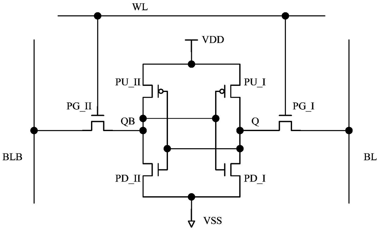
[0046] Figure 4 It is a structural diagram of a storage unit disclosed in the embodiment...


PUM


Abstract

The present application discloses a storage unit. The two MOS transmission gates in the storage unit are double-gate MOS transmission gates. Therefore, when the static noise tolerance test is performed on the above storage unit, it is a bilateral disturbance, so the test intensity is stronger. high.

Description

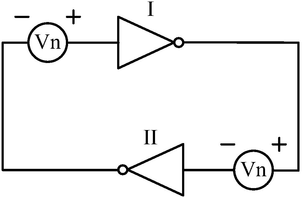
technical field [0001] The present application relates to the technical field of computer chips, and more specifically, to a storage unit, a storage unit defect detection circuit and a memory. Background technique [0002] Memory (Memory) is a memory device in a computer system, used to store programs and data, which consists of multiple storage units for storing binary codes, such as figure 1 As shown, the storage unit is equivalent to a latch constructed by two inverters connected end to end, and each storage unit has its static noise margin. [0003] Such as figure 2 is the schematic diagram of the static noise margin (Static Noise Margin, SNM) of the storage unit, assuming figure 1 When the memory cell in Q stores '1' and QB stores '0', when two noises with opposite polarities are added at Q and QB points, it will store '1' and disturb Vn downward, and store '0' Perturb Vn upward. image 3 is the VTC curve of SNM, image 3 As shown, according to the volt-ampere cha...

Claims


Application Information

Patent Timeline
Patent Type & Authority Patents(China)
IPC IPC(8): G11C29/00
Inventor 杨杨
Owner SPREADTRUM COMM (SHANGHAI) CO LTD
Learn More