
Special-shaped pipe forming method

A molding method and a technology for special-shaped tubes, which are applied to the components of pumping devices for elastic fluids, non-variable-capacity pumps, machines/engines, etc. Simple to use effects

Active Publication Date: 2016-08-03
CHONGQING GENERAL IND (GRP) LTD
View PDF4 Cites 3 Cited by
  • Summary
  • Abstract
  • Description
  • Claims
  • Application Information

AI Technical Summary

Problems solved by technology

[0003] The invention proposes a special-shaped tube forming method, which solves the problem of difficulty in manual forming of special-shaped tubes in the prior art

Method used


Image

  • Special-shaped pipe forming method
  • Special-shaped pipe forming method
  • Special-shaped pipe forming method

Examples


Embodiment Construction

[0036] The following will clearly and completely describe the technical solutions in the embodiments of the present invention with reference to the accompanying drawings in the embodiments of the present invention. Obviously, the described embodiments are only some, not all, embodiments of the present invention. Based on the embodiments of the present invention, all other embodiments obtained by persons of ordinary skill in the art without creative efforts fall within the protection scope of the present invention.

[0037] Such as Figure 5 Shown, special-shaped pipe forming method of the present invention comprises:

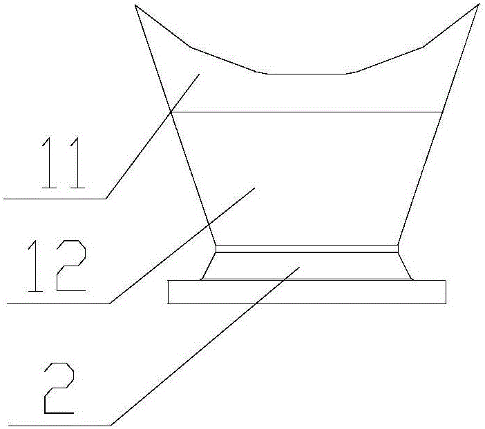
[0038] Step S1, segmenting the special-shaped pipe of the welded casing of the compressor according to a predetermined design. It will be divided into different segments during design, such as Figure 2-4 As shown, the special-shaped pipe therein is divided into a first special-shaped pipe section 11 and a second special-shaped pipe section 12 .

[0039] Step...


PUM


Abstract

The invention relates to the technical field of manufacturing of centrifugal large compressors, and discloses a special-shaped pipe forming method. The special-shaped pipe forming method comprises the following steps: (S1) a special-shaped pipe for welding a shell of a compressor is segmented according to a preset design; (S2) each section is longitudinally split according to preset two split lines; (S3) a lifting pattern is increased in the radial direction of the split lines to reserve a pressing margin; (S4) plates satisfying the shape and the size after the step (S3) are bent and pressed hop by hop according to predesigned marking lines by using pressing and bending molds; (S5) after two plates are bent to shapes corresponding to two parts of the special-shaped pipe sections, each section is welded according to self longitudinal splicing line; and (S6) all the special-shaped pipe sections are welded to form the whole special-shaped pipe. The special-shaped pipe forming method forms each special-shaped pipe section through segmented lofting, pressing and welding, forms the whole special-shaped pipe through welding all the special-shaped pipe sections, and is simple in operation and precise in size.

Description

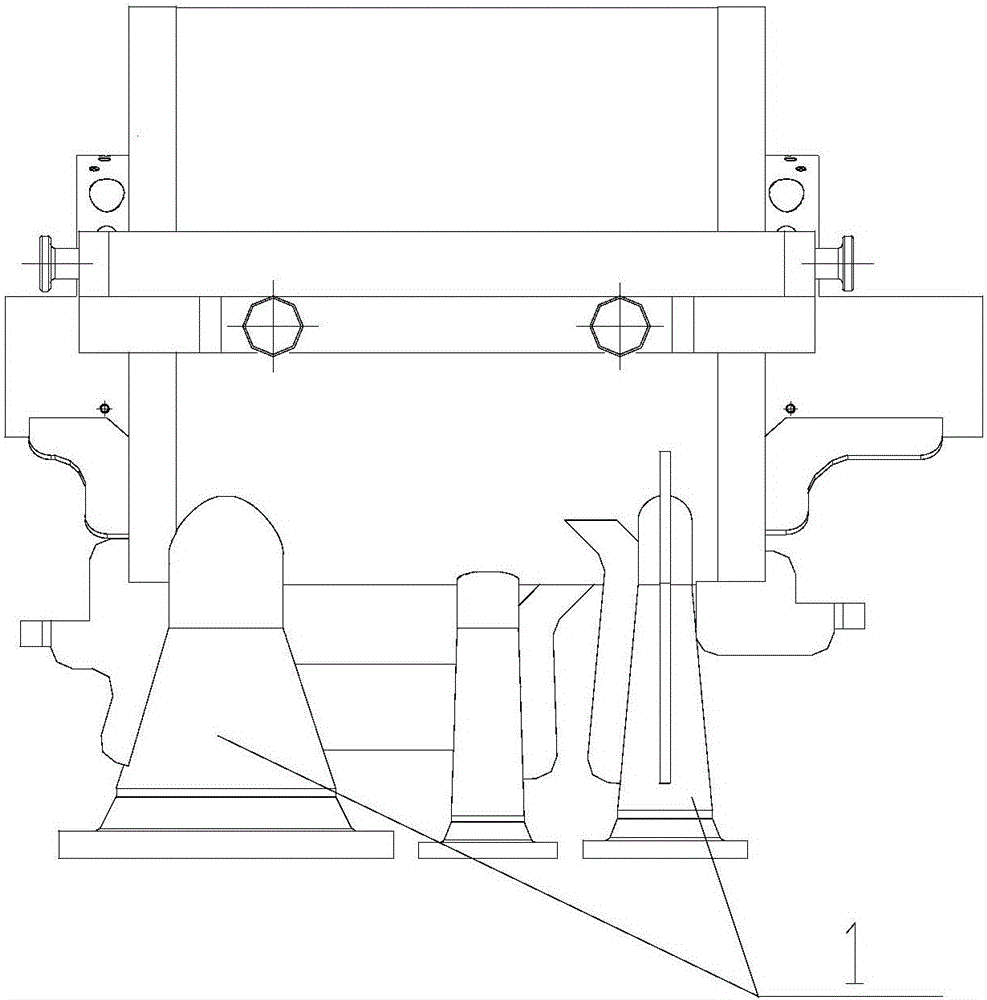
technical field [0001] The invention relates to the technical field of manufacturing large centrifugal compressors, in particular to a method for forming special-shaped pipes. Background technique [0002] At present, the casings of centrifugal large compressors (such as ammonia compressors, propylene compressors, etc.) mainly adopt two structural forms: cast structure or welded structure. When a welded structure compressor casing is used, the forming of its special-shaped tube is one of the technical difficulties of the welded structure casing. Such as figure 1 As shown, the intake and exhaust pipes and air supply pipes of large centrifugal compressors are special-shaped pipes 1. The special-shaped pipes are different sections of the entire pipe with different cross-sectional shapes, or each section has different cross-sectional shapes, that is, the shape of the entire pipe is different. rule. Such as Figure 2-4 As shown, the special-shaped pipe 1 includes two sections...

Claims


Application Information

Patent Timeline
IPC IPC(8): B23P15/00
CPCB23P15/00F04D29/4206
Inventor 刘学刚黄玉堂
Owner CHONGQING GENERAL IND (GRP) LTD
Learn More