
Calibrating device for spinning frame roller side boundary gauge

A calibration device and spinning frame technology, applied in the direction of textiles and papermaking, can solve the problems of increased verticality error, inability to detect or calibrate, and easy wear of cylindrical surfaces, so as to ensure accuracy and technical requirements and improve flat car The effect of quality and easy operation

Active Publication Date: 2016-08-03
ANHUI HUAMAO TEXTILE
View PDF5 Cites 14 Cited by
  • Summary
  • Abstract
  • Description
  • Claims
  • Application Information

AI Technical Summary

Problems solved by technology

After the inspection tool was bought back from the manufacturer, due to the frequent use of the flat car, the cylindrical surfaces of various sizes on the standard rod were easily worn, resulting in an increase in the perpendicularity error with the bottom end surface of the gauge base, which resulted in the detection accuracy of the roller sideline gauge The decline will affect the quality of the equipment flat car
This kind of special inspection tools for textiles does not belong to the national conventional measuring instruments. At present, domestic professional testing institutions cannot test or calibrate this kind of inspection tools, and the accuracy of such special inspection tools cannot be tested in the existing technology of the industry.

Method used


Image

  • Calibrating device for spinning frame roller side boundary gauge
  • Calibrating device for spinning frame roller side boundary gauge
  • Calibrating device for spinning frame roller side boundary gauge

Examples


Embodiment Construction

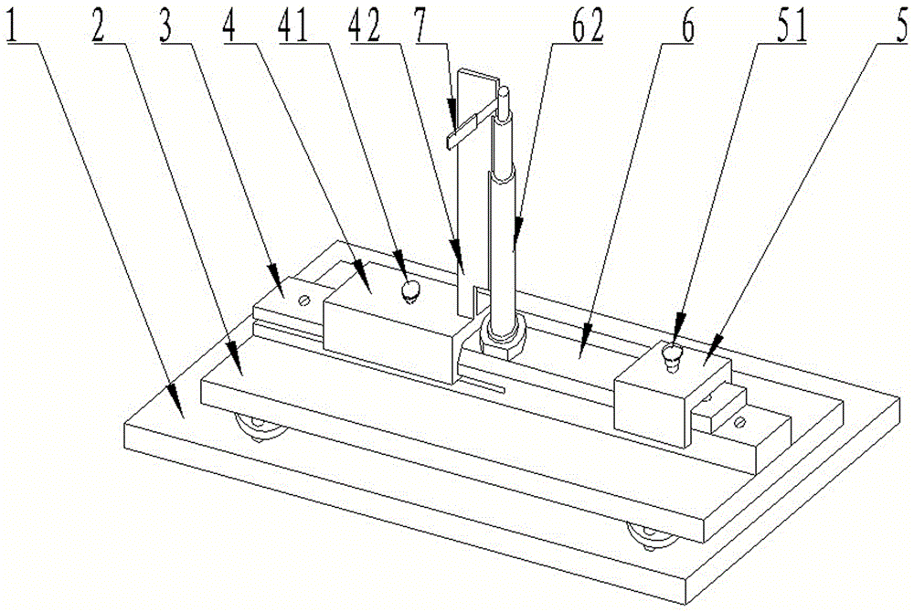
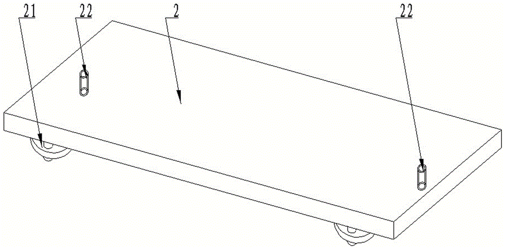
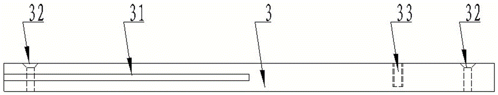
[0022] The verification device of the present invention will be further described in detail below in conjunction with the accompanying drawings.

[0023] Depend on figure 1 , figure 2 , image 3 , Figure 4 , Figure 5 , Figure 6 , Figure 7 , Figure 8 , Figure 9 It can be seen that the device for verifying the roller sidelines of the spinning frame of the present invention comprises a base 1, a detection plate 2 is arranged on the base 1, a parallel block 3 is arranged above the center line of the detection plate 2, and the two sides of the parallel block 3 The left end of the side is provided with a concave groove 31 along the midline, and a detection component 4 is arranged in the concave groove 31. One end of the parallel block 3 is provided with a positioning component 5, and the positioning component 5 is fixed on the parallel block 3 by a positioning bolt 51. Above, a roller sideline gauge 6 is arranged between the detection component 4 and the positioning c...


PUM


Abstract

The invention discloses a calibrating device for a spinning frame roller side boundary gauge. The calibrating device comprises a base, a detection plate is arranged on the base, a parallel block is arranged on the center line of the detection plate, grooves are formed in the left ends of the two side edges of the parallel block along the center line, and a special detection part is arranged in the grooves; a special positioning part is fixedly arranged at one end of the parallel block through a positioning bolt, the roller side boundary gauge is arranged between the special detection part and the special positioning part, the special detection part comprises an n-shaped base, a right-angled tooth-shaped ruler is arranged on the n-shaped base, and a detection end face is arranged on the right-angled tooth-shaped ruler; the roller side boundary gauge comprises a base and a standard rod vertically arranged on the base, and work cylindrical faces in different sizes are arranged on the standard rod; a plug gauge is arranged between the detection end face of the right-angled tooth-shaped ruler and the work cylindrical faces, and leveling bolts are evenly distributed between the detection plate and the base; a parallel groove is formed in the bottom of the n-shaped base, inner buckling claws of bilateral symmetry are arranged at the lower end of the parallel groove, a threaded hole C is formed in the center of a platform on the upper portion of the base, and a locking bolt is arranged in the threaded hole C.

Description

technical field [0001] The invention relates to a verification device for a special inspection tool in the textile industry, in particular to a device for verifying the sidelines of spinning frame rollers. Background technique [0002] In the cotton spinning industry, the roller side line gauge of the spinning frame is a special inspection tool for equipment flat cars. This inspection tool is mainly used to detect the consistent position of the key parts—rollers installed on the frame when the spinning frame is large or small. To ensure the quality of equipment operation after the flat car. After the inspection tool was bought back from the manufacturer, due to the frequent use of the flat car, the cylindrical surfaces of various sizes on the standard rod were easily worn, resulting in an increase in the perpendicularity error with the bottom end surface of the gauge base, which resulted in the detection accuracy of the roller sideline gauge The decline will affect the qual...

Claims


Application Information

Patent Timeline
IPC IPC(8): D01H13/32
CPCD01H13/32
Inventor 郭明
Owner ANHUI HUAMAO TEXTILE
Learn More