Rolling bearing comprising wear ring and related manufacture method

A rolling bearing, anti-wear technology, applied in the direction of rolling contact bearings, rotating bearings, bearings, etc., can solve the problem of increasing the number of bearing components

Inactive Publication Date: 2016-08-03
AB SKF
View PDF4 Cites 2 Cited by
  • Summary
  • Abstract
  • Description
  • Claims
  • Application Information

AI Technical Summary

Problems solved by technology

However, this solution has the disadvantage of increasing the num

Method used


Image

  • Rolling bearing comprising wear ring and related manufacture method
  • Rolling bearing comprising wear ring and related manufacture method
  • Rolling bearing comprising wear ring and related manufacture method

Examples


Embodiment Construction

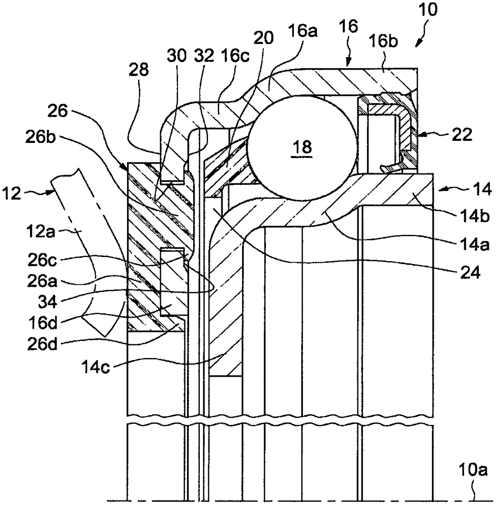
[0024] exist figure 1 , the rolling bearing of which the entire assembly is referenced 10 is intended to be used in a separator release bearing arrangement arranged to act on a diaphragm 12 of a clutch, in particular for a motor vehicle. In this figure, the diaphragm 12 is partially shown and indicated by dashed lines. The diaphragm 12 includes a plurality of rods 12a spaced apart in the circumferential direction. The rolling bearing 10 is intended to be mounted on an operating member (not shown) of an associated separator release bearing arrangement and arranged to move axially.

[0025] Rolling bearing 10 with axis 10a comprises a non-rotating inner ring 14, a rotating outer ring 16, a row of rollers made here in the form of balls and arranged radially between the rolling paths provided on said rings. The member 18, the cage 20 for maintaining the regular circumferential spacing of the rolling members 18, and the annular sealing washer 22 fixed on the outer ring. A rollin...


PUM


Abstract

A rolling bearing comprises an inner ring (14), an outer ring (16), at least one row of rolling elements (18) disposed within a rolling space (24) delimited between said rings, and a wear ring (26) fixed onto one of the rings (16) and comprising a main body (26a) abutted against an outer surface of the ring. The wear ring (26) further comprises at least a column part (26b) extending from the main body (26a) and through a cut-through groove (30) formed in the thickness of the ring. The wear ring (26) also comprises at least one flange (26c) extending from the column part and obtained by local plastic deformation of the column part. The flange extends in the rolling space (24) and reaches an inner surface opposite to the outer surface of the ring.

Description

technical field [0001] The invention relates to the field of rolling bearings used in particular in separator release bearing arrangements intended to act on clutch diaphragms, in particular in motor vehicles. Background technique [0002] Such a device has a rolling bearing of which one ring is rotating and the other ring is fixed, the rotating ring being provided with a radial drive surface for coming into contact with the end of the rod of the clutch diaphragm. [0003] The non-rotating operating member supports a rolling bearing and upon actuation of a control member (mechanical, electrical or hydraulic), moves the bearing axially to bring the drive surface of the rotating ring against the diaphragm of the clutch and actuate the clutch mechanism. [0004] In order to limit the wear caused by the friction between the shaft of the diaphragm and the rotating ring during the operation of the separator and clutch, an anti-wear ring made of synthetic material can be fixed on s...

Claims


Application Information

Patent Timeline
IPC IPC(8): F16C33/30
CPCF16C33/30F16C33/58F16D23/14F16D23/146F16C19/163F16C33/586F16C2361/43
Inventor B·阿诺特P·沃尔特
Owner AB SKF
Why Eureka
Try Eureka