
Union type single tube pass floating head heat exchanger

A single-tube heat exchanger technology, applied to indirect heat exchangers, heat exchanger types, heat exchanger shells, etc., can solve problems such as inconvenient installation and maintenance, high assembly requirements, and sealing leakage, etc., to achieve Easy to disassemble, ensure sealing, and reduce the possibility of leakage

Active Publication Date: 2016-08-03
SINOPEC ENG +1
View PDF5 Cites 7 Cited by
  • Summary
  • Abstract
  • Description
  • Claims
  • Application Information

AI Technical Summary

Problems solved by technology

The structure of the tube box outlet of this floating head heat exchanger is widely used, but because these floating head connectors are all enclosed in the shell, it is inconvenient to install and overhaul, and the expansion joint bears the pressure of the tube side and the shell side at the same time, and the pressure between 5 and 6 The sealing surface between the sealing surface and 3 and 4 needs to ensure the sealing at the same time, which requires high assembly
Therefore, there are often problems such as seal leakage and inconvenient maintenance.

Method used


Image

  • Union type single tube pass floating head heat exchanger
  • Union type single tube pass floating head heat exchanger
  • Union type single tube pass floating head heat exchanger

Examples


Embodiment

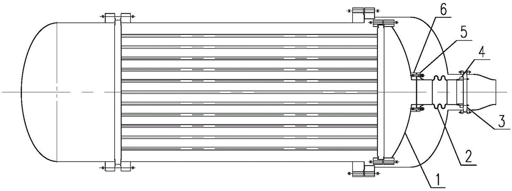
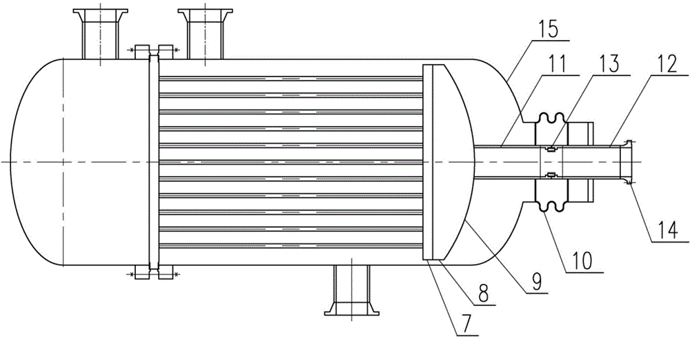
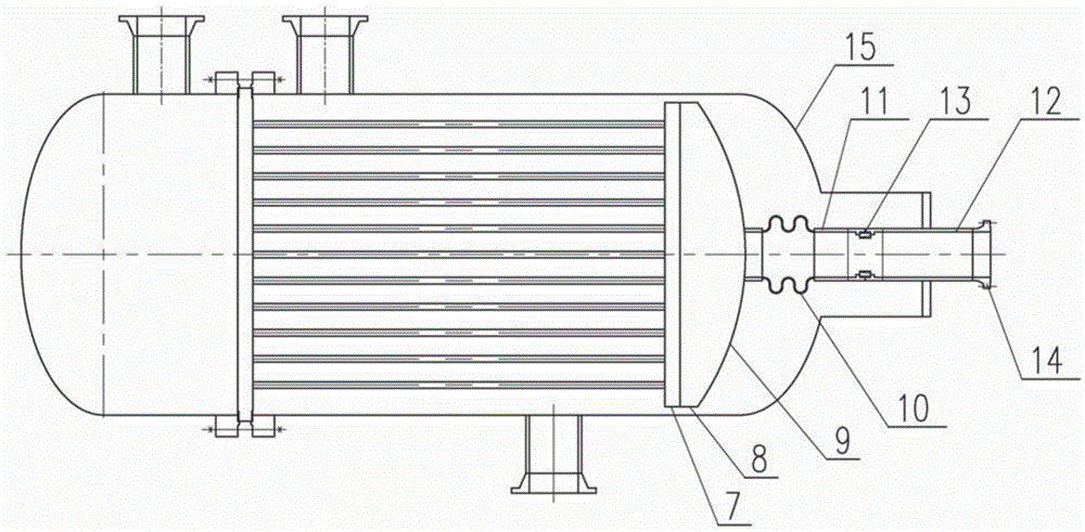
[0048] Such as diagram 2-1 with Figure 2-2 , image 3 As shown, the expansion joint 10 is set on the shell side, and the outer head cover is set to place the short joint of the expansion joint. The floating tube sheet 7 is directly connected with the cylinder body 8 (or head 9) (the cylinder body may not be designed.), and the floating head The connecting pipe 11 on the floating head is directly connected with the sealing head 9, the connecting pipe 12 on the outer head cover is directly connected with the outer head cover 15, and the connecting pipe 11 on the floating head and the connecting pipe 12 on the outer head cover are directly connected by a union 13. Connection terminal 16 is image 3the shape shown. The two connection terminals 16 are installed on an axis, and the two ends are respectively welded to the connecting pipe 11 on the floating head and the connecting pipe 12 on the outer head cover. The inner surface of the end of the connection terminal 16 is proc...


PUM


Abstract

The invention provides a union type single tube pass floating head heat exchanger, and belongs to the heat exchanger field; the tube pass of the union type single tube pass floating head heat exchanger comprises a floating tube plate, a barrel body and a head connected in sequence; the head is connected with a floating head joint pipe; an outer head cover of a shell pass is provided with an outer head cover joint pipe; one portion of the outer head cover joint pipe is positioned on the inner side of the outer head cover, and the other portion extends outside of the outer head cover; on the inner side of the outer head cover, the outer head cover joint pipe and the floating joint pipe are connected through a movable connector; the movable connector comprises two connecting pins, a fixator, a spacing cone, and a locking plug screw or pin bolt; the first end of one connecting pin is connected with the floating joint pipe, the first end of the other connecting pin is connected with the outer head cover joint pipe, and second ends of the two connecting pins are connected through the fixator, the spacing cone, and the locking plug screw or pin bolt.

Description

technical field [0001] The invention belongs to the field of heat exchangers, in particular to a joint-type single-tube-pass floating head heat exchanger. Background technique [0002] The single-tube floating head heat exchanger effectively combines the advantages of the floating head heat exchanger and the fixed tube sheet heat exchanger. It is also suitable for the situation where the pressure drop is small, easy to scale and needs to be cleaned. Commonly used structural types see figure 1 . figure 1 1 is a spherical head, 2 is an expansion joint, 3 is a clamping plate, 4 is a reverse flange, 5 is a pipe flange, and 6 is a flange. The structure of the tube box outlet of the floating head heat exchanger is widely used, but because these floating head connectors are all enclosed in the shell, it is inconvenient to install and overhaul, and the expansion joint bears the pressure of the tube side and the shell side at the same time, and the pressure between 5 and 6 The se...

Claims


Application Information

Patent Timeline
IPC IPC(8): F28D7/16F28F9/00
Inventor 陈昊李英徐小龙
Owner SINOPEC ENG
Features
  • Generate Ideas
  • Intellectual Property
  • Life Sciences
  • Materials
  • Tech Scout
  • Unparalleled Data Quality
  • Higher Quality Content
  • 60% Fewer Hallucinations
Learn More