
A hydraulically controlled flushing box-type wave-making device and method

A wave-making device and punching box technology, which is applied to measuring devices, instruments, and the use of repeated force/pulsation force to test the strength of materials, etc., can solve the problems affecting the accuracy of model test results, troubles in wave model tests, and low frequency of wave simulation. problem, to achieve the effect of authenticity and credibility of the test process, strong comprehensive application ability, and elimination of the influence of reflected waves

Active Publication Date: 2018-11-09
SHANDONG UNIV
View PDF11 Cites 0 Cited by
  • Summary
  • Abstract
  • Description
  • Claims
  • Application Information

AI Technical Summary

Problems solved by technology

The corresponding wave simulation experiment device came into being. The previous wave-making devices were mostly plate-shaped wave-making structures. The reciprocating motion of the wave-making plate will generate reflected waves. The existence of reflected waves in the test channel will distort the expected incident wave field. Distortion of the simulated waves will affect the accuracy of the model test results, which is a problem that has plagued wave model tests for a long time
Some wave-making devices use blowers to create waves, which have inherent defects such as low wave simulation frequency and low control accuracy.
At present, there is no wave-making device that can effectively eliminate the influence of reflected waves and control the amplitude, frequency, and phase of waves in real time.

Method used


Image

  • A hydraulically controlled flushing box-type wave-making device and method

Examples


Embodiment Construction

[0025] The present invention will be further described below in conjunction with the accompanying drawings.

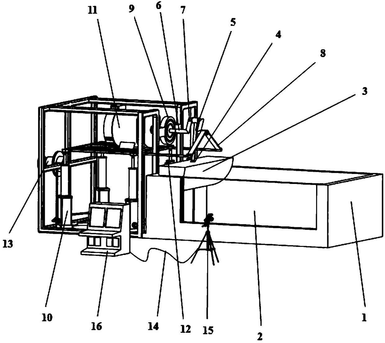
[0026] Such as figure 1 As shown, a hydraulically controlled punching box type wave-making device includes a test channel 1; tempered glass 2; punching box 3; ball joint 4; transmission rod 5; rotating shaft 6; camshaft 7; fixed bracket 8; Hydraulic jack 10; Motor 11; Guide rail 12; Hydraulic controller 13; Data connection line 14; High-speed camera 15; Ocean wave spectrum display 16;

[0027] The punching box 3 is connected with a transmission rod through a ball joint, and the power end of the transmission rod is driven to move up and down by a camshaft 7. The camshaft 7 is connected with the output shaft of the motor 11, and is driven by the motor 11 to rotate, so The motor 11 described above is driven to move up and down by a set of hydraulic drive device, and real-time control of wave amplitude, frequency and phase is realized by adjusting the elevation and rotati...


PUM


Abstract

The invention discloses a hydraulic control punching box type wave generation device and method.The hydraulic control punching box type wave generation device comprises a testing water channel, a hydraulic jack, a punching box, a transmission rod, a cam shaft and a high-speed camera.The hydraulic jack is adjusted, and the height of a wave maker is controller, so that the maximum underwater penetration of the punching box is adjusted, and the cam shaft connected with a rotating shaft of a motor is used for controlling the working stroke of the punching box.A groove-type guide rail is arranged on the rear side of the cylindrical punching box and tightly attached to the rear wall of the testing water channel.The punching box is designed in a cylindrical shape, waves are generated by collision between the punching box and the water surface, and waves generated by the arc structure of the punching box are closer to natural waves.The function of adjusting the wave height, the wave length and the period of the waves is achieved by comprehensively controlling the maximum underwater penetration, stroke and frequency of the punching box.The motor rotates to drive the punching box to move up and down to generate waves, the characteristics of the generated waves can be directly observed through the side wall of tempered glass, and the high-speed camera is fixed to the exterior of the water channel, so that wave information is obtained in real time, and the information is transmitted to an ocean wave spectrum display.

Description

technical field [0001] The invention relates to a hydraulically controlled punching box type wave-making device and method. Background technique [0002] Submarine landslide is a common marine disaster. Through the model test of the influence of waves on the stability of submarine rock slopes in shallow water areas, the slope pressure of submarine rock slopes under the action of waves is studied under the conditions of different slope slopes and structural plane inclination angles. The change law of the structural surface, the distribution law of pore water pressure, stress and displacement in the structural plane, the change law affected by the wave and the change of the boundary water flow on both sides of the structural plane, combined with the test results to discuss the failure process of the rock slope under the action of waves , to guide the establishment of stability analysis methods and slope protection techniques. The corresponding wave simulation experiment devic...

Claims


Application Information

Patent Timeline
Patent Type & Authority Patents(China)
IPC IPC(8): G01N3/36G01N3/02
CPCG01N3/02G01N3/36
Inventor 许振浩潘东东林鹏黄鑫孙超群陈红宾何树江屠文峰刘聪
Owner SHANDONG UNIV
Learn More