
Lens and method for generating vortex beam with converging effect based on metasurface

A metasurface and vortex technology, applied in electrical components, antennas, etc., can solve the problems of low integration and low energy utilization, and achieve the effect of easy integration, high energy utilization, and thin thickness

Active Publication Date: 2018-09-07
HARBIN INST OF TECH
View PDF6 Cites 0 Cited by
  • Summary
  • Abstract
  • Description
  • Claims
  • Application Information

AI Technical Summary

Problems solved by technology

[0003] The purpose of the present invention is to solve the problems of low integration and low energy utilization rate of traditional vortex beam generation methods, thereby providing a lens and method for generating vortex beams with converging effects based on metasurfaces

Method used


Image

  • Lens and method for generating vortex beam with converging effect based on metasurface
  • Lens and method for generating vortex beam with converging effect based on metasurface
  • Lens and method for generating vortex beam with converging effect based on metasurface

Examples


specific Embodiment approach 1

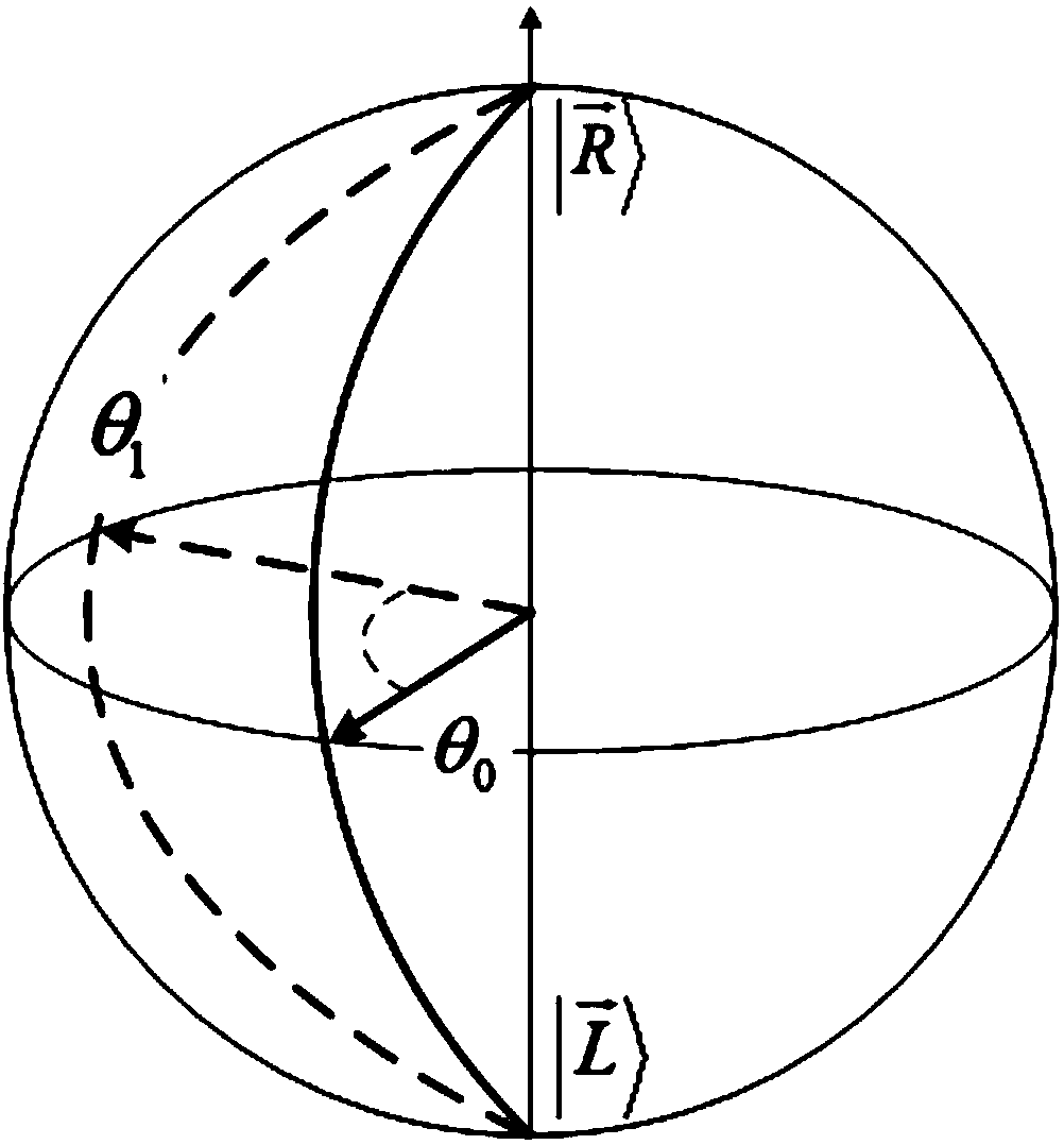
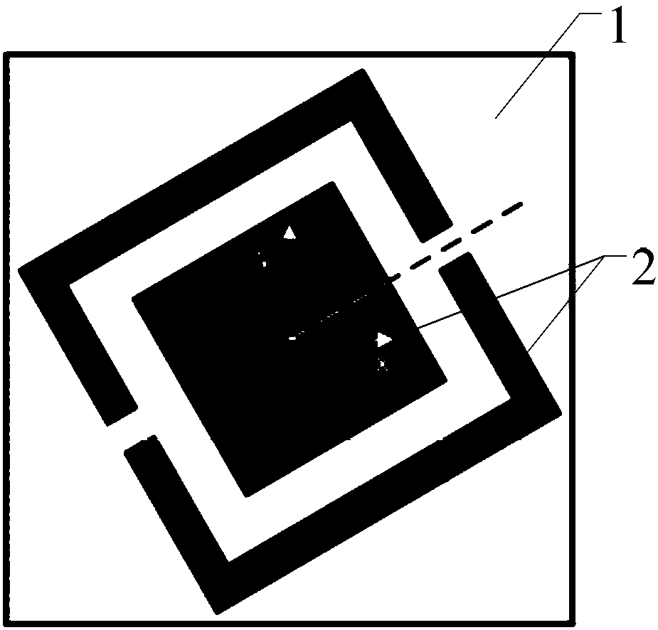
[0023] Specific implementation mode one: combine figure 1 , figure 2 and Figure 5 to Figure 10 Specifically explain this embodiment, the lens for generating a vortex beam with a converging effect based on a metasurface described in this embodiment includes m×n periodically arranged phase mutation units, and both m and n are positive integers;

[0024] Each phase mutation unit includes a substrate 1 and a metal layer 2 located on the surface of the substrate. The metal layer includes two parts, one part is a square metal layer located in the center of the substrate 1, and the other part is a rectangular metal frame surrounding the square metal layer. Metal frame 1 There is a notch in the center of the opposite side of the group, with one side of the substrate as the x-axis, the angle between the center of the notch and the center of the substrate and the positive direction of the x-axis is θ,

[0025]

[0026] Among them, x and y are respectively the abscissa and ordinat...

specific Embodiment approach 2

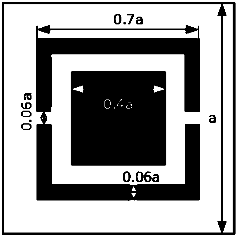
[0042] Specific implementation mode two: combination image 3Describe this embodiment in detail. This embodiment is a further description of the lens that generates a vortex beam with a converging effect based on the metasurface described in Embodiment 1. In this embodiment, the substrate 1 is a square with a side length of a, The side length of the square metal is 0.4a, the side length of the metal frame is 0.7a, the width is 0.06a, the length of the gap is 0.06a, and a is a positive number.

specific Embodiment approach 3

[0043] Specific Embodiment 3: This embodiment is a further description of the lens that generates a vortex beam with a converging effect based on the metasurface described in Specific Embodiment 2. In this embodiment, m and n are both 35.


PUM


Abstract

A lens and a method for generating a vortex beam with a convergence effect based on a super surface relate to a technology for generating a vortex beam with a convergence effect. The invention aims to solve the problem that the traditional vortex beam generation method is of low degree of integration and low utilization rate of energy. The lens comprises m*n periodically-distributed phase mutation units. Each phase mutation unit comprises a substrate and a metal layer on the surface of the substrate. The metal layer is composed of two parts, wherein one part is a square metal layer in the center of the substrate, the other part is a rectangular metal frame surrounding the square metal layer, and a pair of sides of the metal frame is provided with gaps in the center. One side of the substrate is taken as an x axis, and the included angle between the connecting line of the center of one gap and the center of the substrate and the positive direction of the x axis is theta (for the expression, please see the description). Circularly-polarized wave comes in vertically, and the transmitted cross-polarized wave is a vortex beam with a convergence effect. The lens of the invention is thin, easy to integrate and high in utilization rate of energy, and is applicable to generation of a vortex beam with a convergence effect.

Description

technical field [0001] The present invention relates to a technique for generating a vortex beam with converging effect. Background technique [0002] With the rapid development of modern optical communication technology, the expansion of optical data storage capacity has become more and more serious. The traditional vortex beam generation method is to use the spiral phase wave plate, holographic method or liquid crystal method. These methods will greatly reduce the integration degree of the optical communication system or reduce the energy utilization rate in the actual application process. Contents of the invention [0003] The purpose of the present invention is to solve the problems of low integration and low energy utilization rate of traditional vortex beam generation methods, thereby providing a lens and method for generating vortex beams with converging effects based on metasurfaces. [0004] The lens for generating vortex beams with converging effects based on me...

Claims


Application Information

Patent Timeline
Patent Type & Authority Patents(China)
IPC IPC(8): H01Q15/08
CPCH01Q15/08
Inventor 袁乐眙丁旭旻张狂吴群
Owner HARBIN INST OF TECH
Learn More