

Lens and method for generating Bessel beam carrying orbital angular momentum based on super surface
A technology of orbital angular momentum and metasurface, applied in the direction of electrical components, antennas, etc., can solve the problems of high processing precision, poor integration effect, and low energy utilization rate, and achieve high energy utilization rate, easy integration, and thin thickness Effect
- Summary
- Abstract
- Description
- Claims
- Application Information
AI Technical Summary
Problems solved by technology
Method used
Image

Examples
specific Embodiment approach 1
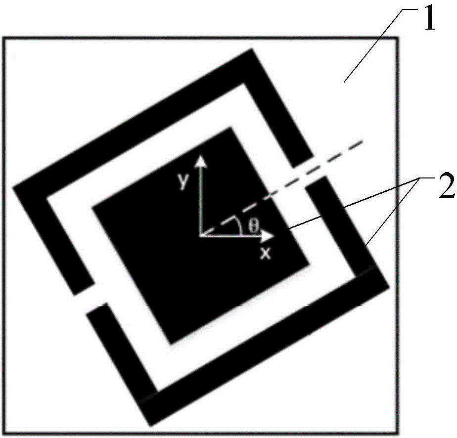
[0027] Specific implementation mode one: combine figure 1 , figure 2 and Figure 5 to Figure 14 This embodiment is described in detail. The metasurface-based lens that generates a Bessel beam carrying orbital angular momentum described in this embodiment includes m×n periodically arranged phase mutation units, and both m and n are positive integers;
[0028] Each phase mutation unit includes a substrate 1 and a metal layer 2 located on the surface of the substrate. The metal layer includes two parts, one part is a square metal layer located in the center of the substrate 1, and the other part is a rectangular metal frame surrounding the square metal layer. Metal frame 1 There is a notch in the center of the opposite side of the group, with one side of the substrate as the x-axis, the angle between the center of the notch and the center of the substrate and the positive direction of the x-axis is θ,
[0029] θ = 1 2 ...
specific Embodiment approach 2
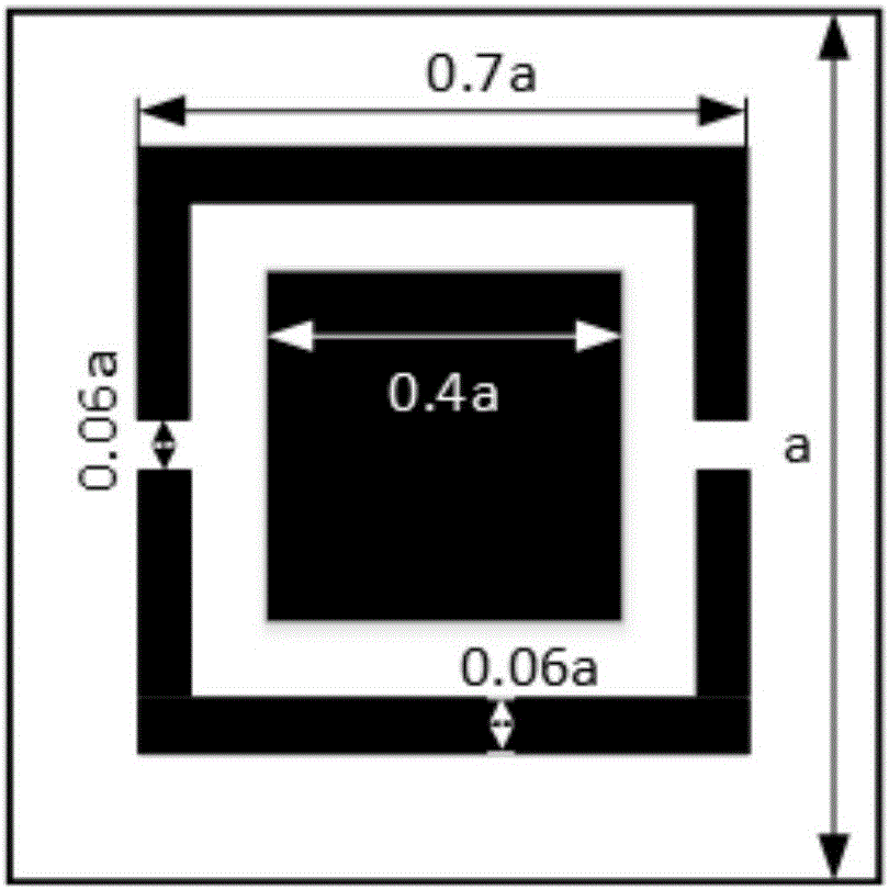
[0046] Specific implementation mode two: combination image 3 Describe this embodiment in detail. This embodiment is to further illustrate the lens that generates a Bessel beam carrying orbital angular momentum based on the metasurface described in Embodiment 1. In this embodiment, the substrate 1 is a square with a side length of a, the side length of the square metal is 0.4a, the side length of the metal frame is 0.7a, the width is 0.06a, the length of the gap is 0.06a, and a is a positive number.
specific Embodiment approach 3
[0047] Embodiment 3: This embodiment is a further description of the lens that generates Bessel beams carrying orbital angular momentum based on the metasurface described in Embodiment 2. In this embodiment, both m and n are 35.
PUM
| Property | Measurement | Unit |
|---|---|---|
| Thickness | aaaaa | aaaaa |
Abstract
Description
Claims
Application Information