
Subframe structure

A sub-frame and frame technology, which is applied to the substructure, vehicle components, jet propulsion devices, etc., can solve the problems of small mass, the area that cannot be vibrated and the partition area is enlarged, and the thickness and diameter of the circular plates 3a and 3b are increased. The effect of reducing the resonance frequency, improving the anti-vibration effect, and increasing the vibration isolation area

Active Publication Date: 2017-12-12
HONDA MOTOR CO LTD
View PDF7 Cites 0 Cited by
  • Summary
  • Abstract
  • Description
  • Claims
  • Application Information

AI Technical Summary

Problems solved by technology

[0008] However, when the vibration-absorbing elastic body 1 disclosed in Patent Document 1 is arranged on the sub-frame to block the transmission of vibration generated from a vehicle power plant such as an engine, for example, the disc functioning as a mass component The mass of 3a, 3b is relatively small, and it is difficult to significantly increase the thickness and diameter of the discs 3a, 3b due to the relationship with the elastic body 2a, 2b
Therefore, in the vibration-absorbing elastic body 1 disclosed in Patent Document 1, there is a problem that the relationship between the spring constant (k) and the mass (m) at a known predetermined resonance frequency (f) In this case, the vibration isolation area in the resonance frequency characteristic cannot be increased

Method used


Image

  • Subframe structure
  • Subframe structure
  • Subframe structure

Examples


Embodiment Construction

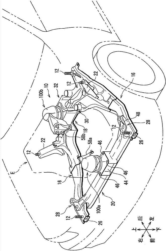
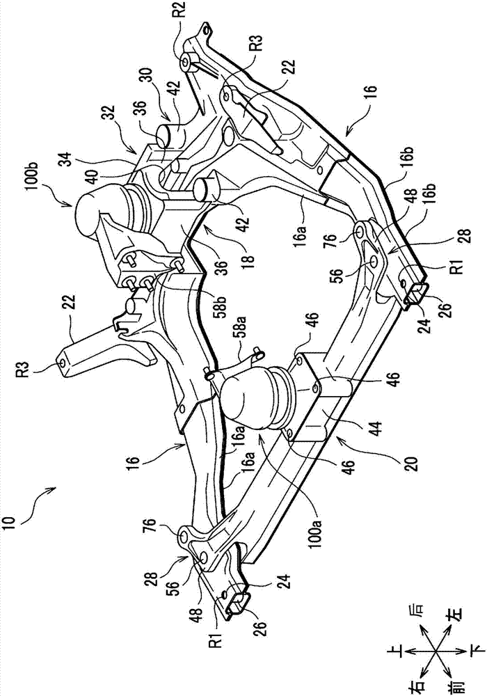
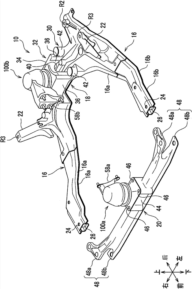
[0032] Next, embodiments of the present invention will be described in detail with reference to the drawings as appropriate. figure 1 It is a transparent perspective view showing a state in which a subframe structure to which a subframe structure according to an embodiment of the present invention is applied is arranged at a front portion of a motor vehicle, figure 2 yes figure 1 The perspective view of the subframe structure shown, image 3 yes figure 2 An exploded perspective view of the subframe structure shown, Figure 4 yes figure 2 A top view of the subframe structure shown, Figure 5 yes figure 2 Side view of the subframe structure shown. In each figure, "front and rear" and "up and down" indicated by arrows indicate the front and rear directions and up and down directions of the vehicle, and "left and right" indicate the left and right directions (vehicle width direction) viewed from the driver's seat.

[0033] Such as figure 1 As shown, the subframe str...


PUM


Abstract

The present invention provides a sub-frame structure comprising left and right side beams (16) extending in the front-rear direction of the vehicle and a rear beam (18) extending in the vehicle width direction, the sub-frame structure supporting an engine, etc. via an anti-vibration device A power plant for a vehicle, and the subframe structure is supported by a vehicle frame, wherein the left and right side members (16) are rigidly fixed to the vehicle frame (14) via bolts (12), and the front cross member (20) is loaded with The first anti-vibration device, the auxiliary frame structure is equipped with a first bush and a second bush, so as to support the front beam (20) on the left and right side beams in a floating manner.

Description

technical field [0001] The present invention relates to a subframe structure provided at the front of a vehicle such as a motor vehicle. Background technique [0002] A vehicle such as a motor vehicle is provided with a subframe, which is fixed to a front side frame as a frame, has suspension components such as suspension arms and stabilizers attached thereto, and supports the engine via a vibration-proof device. And / or motors and other vehicle power devices. [0003] For example, if Figure 12 As shown, Patent Document 1 discloses a vibration-absorbing elastic body 1 made of rubber that absorbs vibrations generated in a vehicle body. This vibration-absorbing elastic body 1 includes: two cylindrical elastic bodies 2a, 2b; and metal discs 3a, 3b interposed between the lower sides of the two elastic bodies 2a, 2b, respectively. It should be noted that, in Figure 12 Among them, reference numeral 4 denotes left and right brackets, reference numeral 5 denotes a beam, and refer...

Claims


Application Information

Patent Timeline
Patent Type & Authority Patents(China)
IPC IPC(8): B62D21/00B60K5/12
CPCB60K5/12B60K5/1216B62D21/11
Inventor 平野正隆宫原哲也
Owner HONDA MOTOR CO LTD
Learn More