Workpiece feeding rack limiting device for intelligent robot rolled hemming system

A technology of robot intelligence and rolling hemming, which is applied in the direction of positioning device, feeding device, storage device, etc., can solve the problems of rolling equipment damage, occupying a lot of land, and large economy, so as to achieve the effect of flexible production

Active Publication Date: 2016-08-10
GUANGZHOU RISONG HOKUTO AUTOMOTIVE EQUIP CO LTD
View PDF7 Cites 7 Cited by
  • Summary
  • Abstract
  • Description
  • Claims
  • Application Information

AI Technical Summary

Problems solved by technology

When using traditional molds and presses for stamping and hemming, since the hemming contour of the outer panel changes according to the shape of the vehicle body, the angle of hemming along the entire contour is also different, and the area where the hemming transition is sharp and the hemming angle is too high For large areas, hemming will be very difficult
At the same time, traditional stamping hemming molds occupy a lot of land, have high cost and poor flexibility. In order to shorten the automobile development cycle and improve product competitiveness, new inner and outer panel connection technology and robot hemming technology are gradually applied in body production
[0003] In the robot intelligent rolling hemming system, the guidance and positioning accuracy of the workpiece directly affect the rolling quality of the workpiece, and even cause damage to the rolling equipment, resulting in huge economic benefits

Method used


Image

  • Workpiece feeding rack limiting device for intelligent robot rolled hemming system

Examples


Embodiment Construction

[0014] The present invention and the technical solutions in the embodiments of the present invention will be clearly and completely described below in conjunction with the accompanying drawings.

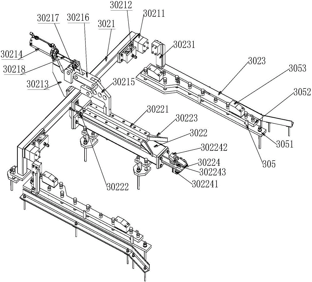
[0015] Such as figure 1 As shown in the figure, a limit device for an upper frame of a robotic intelligent rolling hemming system includes an X-direction limit frame 3021, which is a rod and is fixed and installed on the ground through anchor bolts. The two ends of one side of the limit frame 3021 along the X direction are respectively provided with an X-direction pressure block 30211 of the loading table and an X-direction side proximity switch 30212 of the loading table for detecting the position of the loading table;

[0016] The X-direction limit frame 3021 is equipped with an X-direction limit cylinder mounting plate 30213 in the middle of the X-negative direction side, and is arranged along the X-direction. The X-direction limit cylinder 30214 of the upper piece table, one end...


PUM


Abstract

The invention discloses a workpiece feeding rack limiting device for an intelligent robot rolled hemming system. The workpiece feeding rack limiting device comprises an X-direction limiting rack, wherein workpiece feeding table X-direction pressing blocks and workpiece feeding table X-direction side proximity switches are separately arranged at two ends of the X-direction limiting rack; an X-direction limiting air cylinder mounting plate is arranged in the middle of the X-direction limiting rack; a workpiece feeding table X-direction limiting air cylinder and a workpiece feeding table X-direction pressing head are arranged on the X-direction limiting air cylinder mounting plate; a workpiece feeding table X-direction middle guide frame is also arranged in the middle of the X-direction limiting rack; an X-direction guide groove and a workpiece feeding table X-direction middle proximity switch are formed in the upper surface of the workpiece feeding table X-direction middle guide frame; a workpiece feeding table muzzle brake is arranged at the tail end of the workpiece feeding table X-direction middle guide frame; the rack limiting device also comprises two Y-direction limiting racks; workpiece feeding table supporting frames are respectively arranged at the inner sides of the Y-direction limiting racks. According to the workpiece feeding rack limiting device disclosed by the invention, accurate positioning of the workpiece feeding rack of the intelligent robot rolling and hemming system is realized by accurate guiding in X, Y and Z directions; meanwhile, information about workpieces is acquired by sensing a signal of the workpiece feeding rack and is fed back to a master controller, and flexible production is realized.

Description

technical field [0001] The invention belongs to the field of mechanical manufacturing. The invention relates to an inner and outer panel hemming system in automobile manufacturing, in particular to a limit device for an upper part stand of a robot intelligent rolling hemming system. Background technique [0002] At present, the connection of the inner and outer panels of the automobile body door cover usually uses the hemming process. When using traditional molds and presses for stamping and hemming, since the hemming contour of the outer panel changes according to the shape of the vehicle body, the angle of hemming along the entire contour is also different, and the area where the hemming transition is sharp and the hemming angle is too high In a large area, it will be very difficult to wrap the edge. At the same time, traditional stamping hemming molds occupy a large area, are costly, and have poor flexibility. In order to shorten the automobile development cycle and impr...

Claims


Application Information

Patent Timeline
Patent Type & Authority Applications(China)
IPC IPC(8): B21D43/00B21D39/02
CPCB21D39/023B21D43/003
Inventor 颜雪涛陈国金
Owner GUANGZHOU RISONG HOKUTO AUTOMOTIVE EQUIP CO LTD
Why Eureka
Try Eureka