Motor driving apparatus
A technology for motor driving and driving part, which is applied to electric devices, motor vehicles, electric vehicles, etc., can solve problems such as sensor sticking, and achieve the effect of suppressing excessive driving.
- Summary
- Abstract
- Description
- Claims
- Application Information
AI Technical Summary
Problems solved by technology
Method used
Image

Examples
Embodiment approach 1
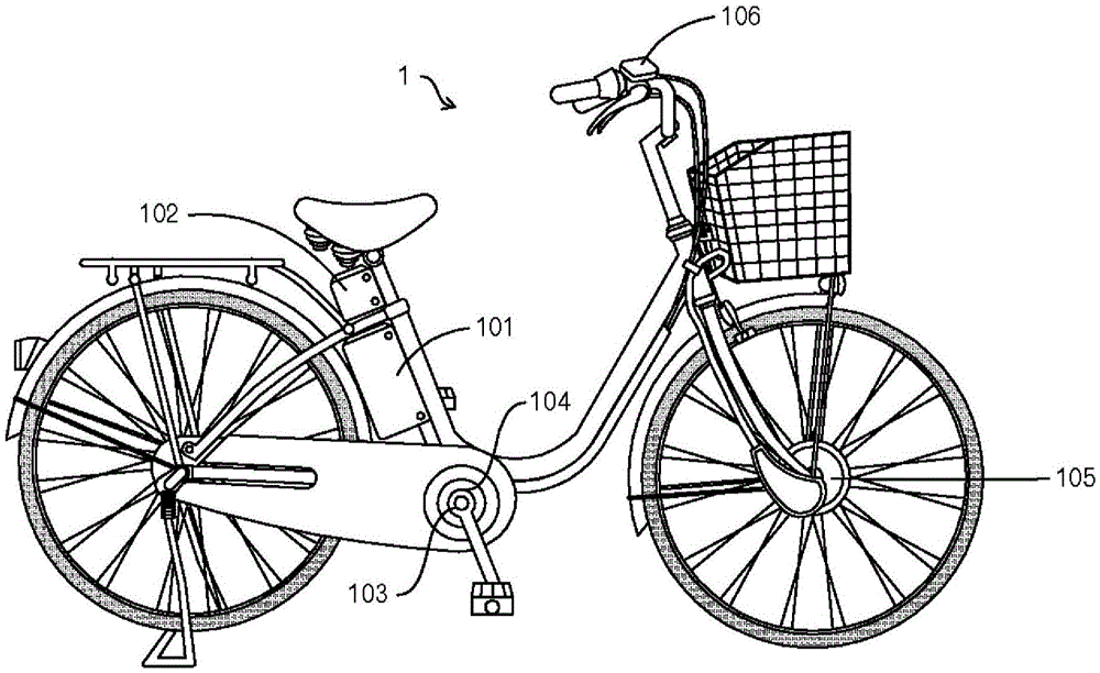
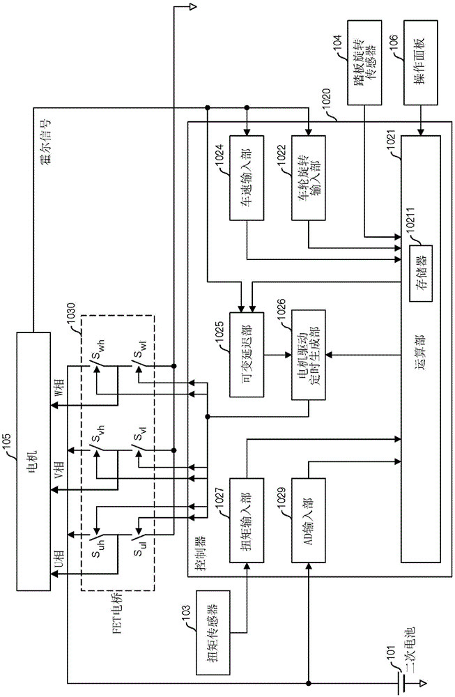
[0033] figure 1 It is an external view showing an example of a bicycle with a motor as an electric assist vehicle in this embodiment. The motorized bicycle 1 is equipped with a motor drive device. The motor drive device has a secondary battery 101 , a motor drive controller 102 , a torque sensor 103 , a pedal rotation sensor 104 , a motor 105 , and an operation panel 106 . In addition, the bicycle 1 with a motor also has a free wheel and a transmission.
[0034] The secondary battery 101 is, for example, a lithium-ion secondary battery with a maximum supply voltage (voltage when fully charged) of 24V, but may be another type of battery, such as a lithium-ion polymer secondary battery, a nickel-metal hydride storage battery, or the like.
[0035] The torque sensor 103 is installed on a wheel mounted on the crankshaft, detects the driver's pedal force, and outputs the detection result to the motor drive controller 102 . Further, the pedal rotation sensor 104 is provided on a ...
Embodiment approach 2
[0109] Figure 6 A configuration example of the boost suppression control unit 1210 of the present embodiment is shown. The boost suppression control unit 1210 according to this embodiment includes an initial masking unit 2101, an accumulated distance input unit 2102, a parking detection unit 2103, a first consumed distance input unit 2104, a second consumed distance input unit 2105, a remaining distance limiting unit 2106, Road modulator 2107, travel distance register 2108, allowable distance register 2109, determination section 2113, and adders 2110 to 2112.
[0110] The cumulative distance input unit 2102 outputs the cumulative distance corresponding to the pedal pulse output from the pedal rotation sensor 104 according to the rotation of the pedal. The accumulation distance is the same as that of the first embodiment.
[0111] When the adder 2110 receives the output of the accumulated distance from the accumulated distance input part 2102, the accumulated distance and th...
Embodiment approach 3
[0134] Figure 8 A configuration example of the boost suppression control unit 1210 of the present embodiment is shown. The boost suppression control unit 1210 of this embodiment has an initial mask unit 2201, a converted vehicle speed detection unit 2202, an upper limit limiter 2203, a vehicle speed input unit 2204, a lower limit limiter 2205, a parking detection unit 2206, an allowable remaining distance register 2207, a determination Section 2208 and adders 2209 and 2210.
[0135] In the third embodiment, instead of calculating with a fixed accumulated distance and consumed distance for each pulse of the pedal and / or the motor, the pedal-converted vehicle speed and the vehicle speed are integrated at predetermined calculation frame time intervals (for example, 150 Hz) form for processing. The pedal-converted vehicle speed is regarded as the timed accumulation distance of each calculation frame, and the vehicle speed (specifically, the converted speed of the motor drive wh...
PUM
 Abstract
Description
Claims
Application Information
 - R&D
- Intellectual Property
- Life Sciences
- Materials
- Tech Scout
- Unparalleled Data Quality
- Higher Quality Content
- 60% Fewer Hallucinations
Browse by: Latest US Patents, China's latest patents, Technical Efficacy Thesaurus, Application Domain, Technology Topic, Popular Technical Reports.
© 2025 PatSnap. All rights reserved.Legal|Privacy policy|Modern Slavery Act Transparency Statement|Sitemap|About US| Contact US: help@patsnap.com