Eddy current vibration device

A vibrating device and driving device technology, which is applied to vibration generating devices, drilling with vibration, wellbore/well components, etc., can solve the problems of short service life, low vibration efficiency, high vibration frequency, etc., and achieve excellent vibration effect and high pressure. The effect of low consumption and long service life

Inactive Publication Date: 2019-04-19
邓福成 +1
View PDF10 Cites 0 Cited by
  • Summary
  • Abstract
  • Description
  • Claims
  • Application Information

AI Technical Summary

Problems solved by technology

[0004] The technical problem to be solved by the present invention is to provide an eddy current vibration device, which can achieve a better vibration effect without an additional vibrator. The vibration frequency is too high, the vibration efficiency is low, and the service life of the whole device is short

Method used


Image

  • Eddy current vibration device
  • Eddy current vibration device
  • Eddy current vibration device

Examples


Embodiment Construction

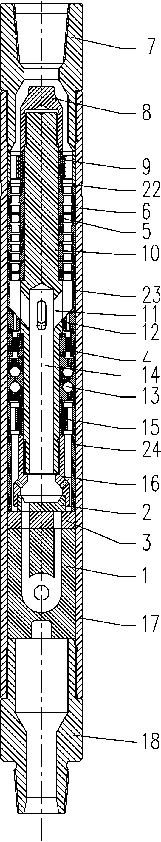
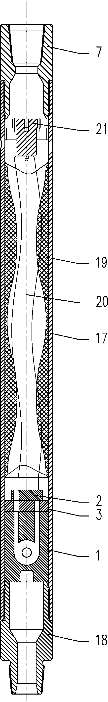
[0045] Such as Figure 1~5 Among them, an eddy current vibration device includes a housing 17, the upper end of the housing 17 is connected to the upper joint 7, and the lower end is connected to the upper joint 7, see figure 1 , 2 middle.

[0046] The housing 17 is provided with a movable valve plate 2 driven to rotate by the driving device, and the vibrating device 1 is provided with a circular vortex chamber 103, specifically, the vortex chamber 103 is cylindrical. At least one liquid inlet groove 101 is connected tangentially to the vortex cavity 103, and the center of the vortex cavity 103 is provided with a vortex cavity outlet 104, and the vortex cavity outlet 104 is connected to the liquid outlet 105; when the high-pressure liquid flow hits the vortex cavity 103, a Vibration, and then the liquid flow is discharged from the outlet 104 of the vortex chamber.

[0047] At least one bypass channel 102 is connected to the liquid outlet 105; when the liquid flows out from ...


PUM


Abstract

The invention provides a vortex vibration device. The vortex vibration device comprises a casing, wherein a movable valve plate driven by a driving device to rotate is arranged in the casing, a round vortex chamber is formed in the vibration device, at least one liquid inlet groove is tangentially connected with the vortex chamber, and a vortex chamber outlet is formed in the center of the vortex chamber and connected with a liquid outlet; at least one bypass channel is connected with the liquid outlet; a movable valve liquid inlet hole is formed in the movable valve plate and is communicated with the liquid inlet groove and the bypass channel alternately. With adoption of the structure, the vortex vibration device has the beneficial effects as follows: liquid flow entering the vortex chamber and the bypass channel is changed by movable valve plate and fixed valve plate assemblies, the vibration effect caused by a vortex effect produced in the vortex chamber is better than that caused by open area changes, the vibration effect of the whole vortex vibration device is more obvious, and matching with a spring nipple or a jar in a drilling process is not needed.

Description

technical field [0001] The invention relates to the fields of petroleum and natural gas exploitation and drilling tools, in particular to an eddy current vibration device. Background technique [0002] With the wide application of highly deviated wells and horizontal wells, during the drilling process, due to the self-weight of the drilling tool, the friction between the drilling tool and the well wall during drilling is large, resulting in the back pressure of the drilling tool, which seriously affects the drilling of horizontal wells Therefore, reducing friction, increasing dynamic drilling pressure and improving drilling efficiency are urgent problems to be solved in current drilling engineering. It has been found through research that by applying appropriate periodic axial vibration to the drill string, the static friction between the drill string and the well wall can be changed into dynamic friction, which can greatly reduce the friction resistance in the drilling proc...

Claims


Application Information

Patent Timeline
Patent Type & Authority Patents(China)
IPC IPC(8): E21B28/00E21B7/24
CPCE21B7/24E21B28/00
Inventor 邓福成张策
Owner 邓福成
Why Eureka
Try Eureka