Linear vibration motor

a linear vibration and motor technology, applied in mechanical vibration separation, dynamo-electric machines, electrical equipment, etc., can solve the problems of limited vibration effect and detrimental to the reliability of the vibration motor

Active Publication Date: 2020-07-14
AAC TECH PTE LTD
View PDF21 Cites 27 Cited by
  • Summary
  • Abstract
  • Description
  • Claims
  • Application Information

AI Technical Summary

Benefits of technology

[0030]Compared with related art, the linear vibration motor of the present utility model is provided with multiple elastic pieces which are respectively fixed on two opposite sides of the vibration unit along its vibration direction, the elastic piece has a N-shape structure with big stroke and low stress, thus improving its elastic performance and service life and provide good vibration performance of the linear vibration motor; the two elastic pieces on the same side are provided reversely to from a dual-layer structure mounted reversely, thus effectively increasing rigidity of the vibration motor on the Y-axis and Z-axis directions and prevent the vibration unit to shake toward the Y-axis direction in vibration; meanwhile, the multiple elastic pieces form a configuration of dual-layer central symmetric structure, reduce the vibration shift and shake toward the Y-axis direction of the vibration unit in operation, thus improving the reliability of the linear vibration motor.

Problems solved by technology

However, in the linear vibration motor of related art, although two elastic pieces are provided symmetrically, the elastic piece of U-shape structure has a relatively high stroke tension, resulting in its limited vibration effect; in addition, although the above structure is provided so that the linear vibration motor makes X-axis (horizontal direction) vibration, a problem of big shake exists on Y-axis and Z-axis, which is detrimental to the reliability of the vibration motor.

Method used


Image

  • Linear vibration motor
  • Linear vibration motor

Examples


Embodiment Construction

[0012]The present disclosure will hereinafter be described in detail with reference to an exemplary embodiment. To make the technical problems to be solved, technical solutions and beneficial effects of the present disclosure more apparent, the present disclosure is described in further detail together with the figure and the embodiment. It should be understood the specific embodiment described hereby is only to explain the disclosure, not intended to limit the disclosure.

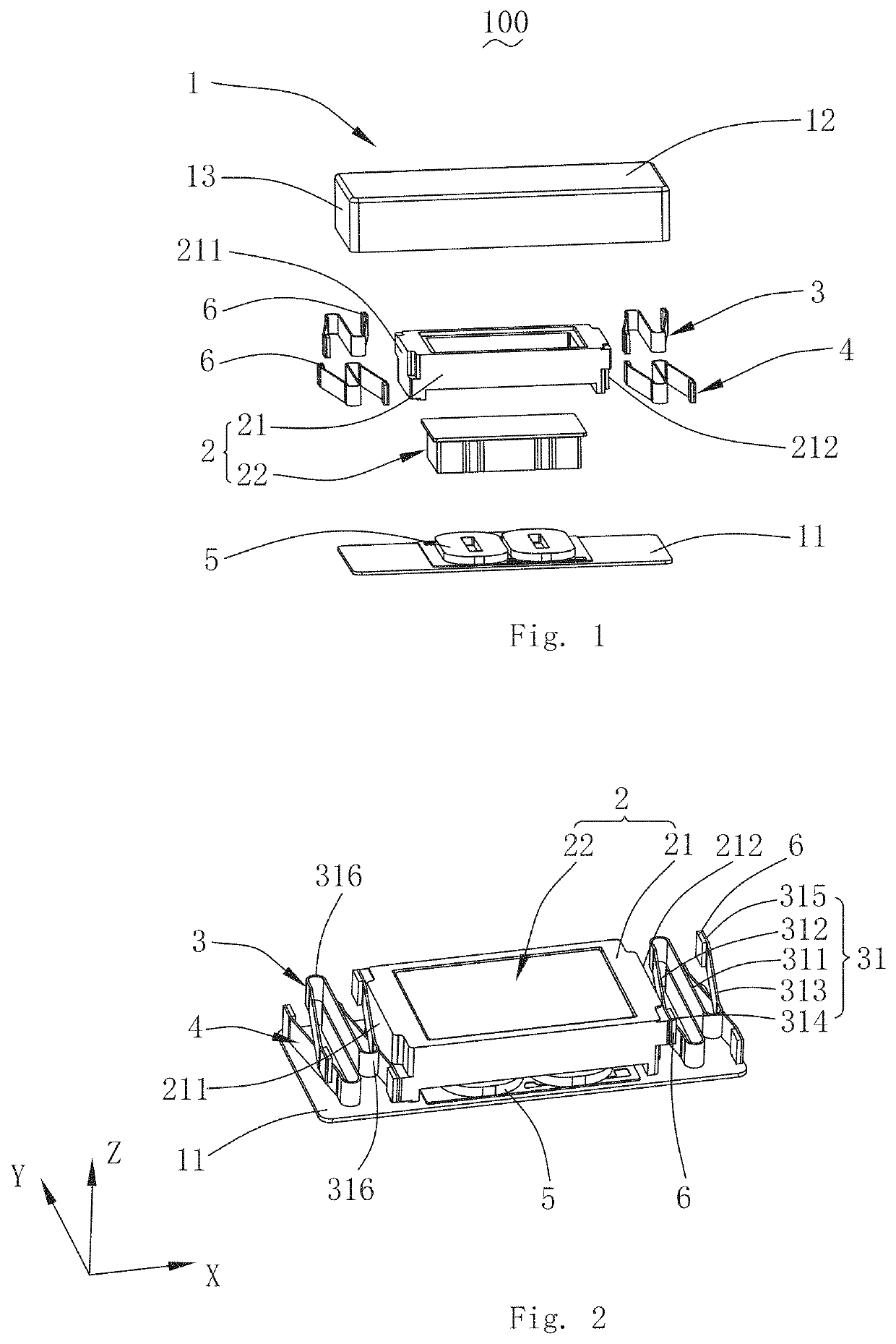
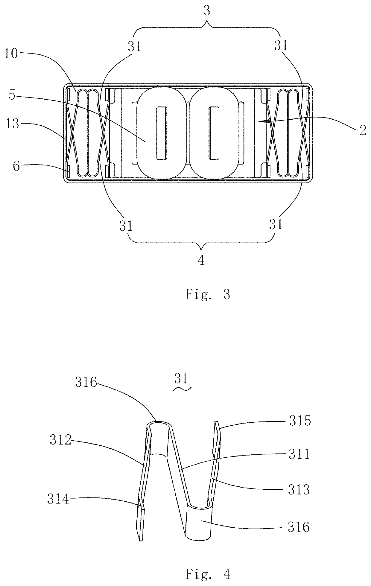
[0013]Referring to FIGS. 1-4, the present disclosure provides a linear vibration motor 100. The linear vibration motor 100 comprises a base 1 with an accommodation space 10, a vibration unit 2, a first elastic unit3 and a second elastic unit 4 fixing and suspending the vibration unit 2 in the accommodation space 10, and a coil 5 fixed to the base 1 and driving the vibration unit 2 to vibrate.

[0014]The base 1 comprises a bottom plate 11, a top plate 12 opposite to the bottom plate 11, and a side plate 13 connecting ...


PUM


Abstract

A linear vibration motor includes a base including an accommodation space; a vibration unit; and a first elastic unit suspending the vibration unit in the accommodation space. The first elastic unit includes two elastic pieces located on two opposite sides of the vibration unit, each the elastic piece having a main elastic arm, a first auxiliary elastic arm and a second auxiliary elastic arm extending reversely in a bending way respectively from an end of the first auxiliary elastic arm and an end of the second auxiliary elastic arm. The main elastic arm is perpendicular to the vibration direction, the first auxiliary elastic arm and the second auxiliary elastic arm are respectively located on the two opposite sides of the main elastic arm, the first fixed arm is fixed to the vibration unit, and the second fixed arm is fixed to the base.

Description

FIELD OF THE PRESENT DISCLOSURE[0001]The present disclosure relates to vibration motors, more particularly to a linear vibration motor having a vibration unit vibrating along a horizontal direction.DESCRIPTION OF RELATED ART[0002]With the development of electronic technologies, portable consumable electronic products are increasingly popular, such as mobile phone, handheld game console, navigating device or handheld multimedia entertainment equipment, in which a vibration motor is generally used for system feedback, such as call reminder, message reminder, navigation reminder of mobile phone, vibration feedback of game console. To meet the demand of such a wide application, the vibration motor shall have high performance and long life.[0003]A linear vibration motor of related art comprises a base with an accommodation space, a vibration unit located in the accommodation space, elastic pieces respectively fixed on two sides of the vibration unit for suspending the vibration unit in t...

Claims


Application Information

Patent Timeline
Patent Type & Authority Patents(United States)
IPC IPC(8): B06B1/04H02K33/02H02K33/00H02K33/12
CPCB06B1/045H02K33/02H02K33/12
Inventor HUANG, JINQUANXU, HONGFULING, FANGHUAWANG, JUNSHENG
Owner AAC TECH PTE LTD
Why Eureka
Try Eureka