
Pressure relief guide device for oil well wellhead

A flow diversion device and oil well technology, which is applied in wellbore/well valve devices, wellbore/well parts, earthwork drilling and production, etc., which can solve the problems of slow pressure passage, poor fluid passage capacity, and prolonged pressure release time, etc. , to achieve the effect of rapid discharge

Inactive Publication Date: 2016-08-10
DAQING YINNIMEILI MACHINERY EQUIP MFG
View PDF7 Cites 0 Cited by
  • Summary
  • Abstract
  • Description
  • Claims
  • Application Information

AI Technical Summary

Problems solved by technology

Since most of the channels are below 30 mm, the passing capacity is poor, and due to the action of the spring, the opening of the channel is limited, causing the pressure to pass slowly
2. Blockage of the constant pressure release channel: During normal production, the constant pressure release channel mainly passes through gas, and the flow rate is small
In the long-term production process, due to the fouling and waxing of the channel, the passage is narrow, the fluid passing capacity becomes poor, and the pressure release time is prolonged.

Method used


Image

  • Pressure relief guide device for oil well wellhead
  • Pressure relief guide device for oil well wellhead
  • Pressure relief guide device for oil well wellhead

Examples


Embodiment Construction

[0016] The present invention will be further described below in conjunction with accompanying drawing:

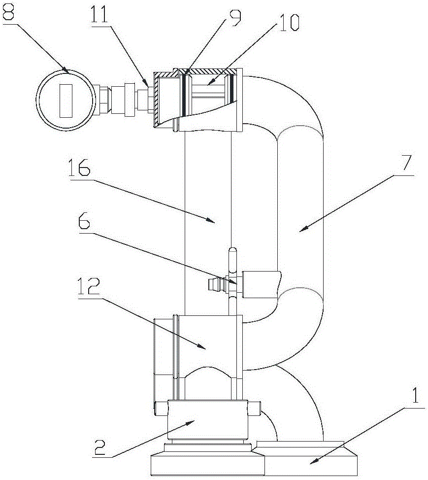
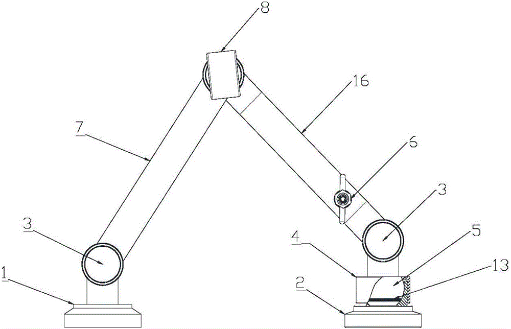
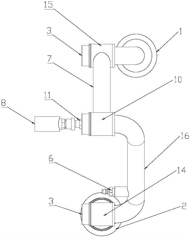
[0017] Depend on Figure 1 to Figure 5 As shown, an oil well wellhead pressure relief and diversion device includes a clamp seat 1, an elbow on the clamp seat 1 is connected to a three-width rotary joint C15, and a folded pipe is connected to the three-width rotary joint C15 through an outer jacket 12 A7, so that the folding tube A7 can freely rotate relative to the clamp seat 1. The other end of the folding tube A7 is connected to the three-width rotary joint A10 through another jacket, and the three-width rotary joint A10 is connected to the folding tube B16 through an elbow, so that the folding tube B16 and the folding tube A7 can rotate freely. The other end of the folded tube B16 is connected to the three-width rotary joint B14 through an elbow, and the other end of the three-width rotary joint B14 is connected to the deviation adjustment ball 5 through the jacket 12,...


PUM


Abstract

The invention relates to a wellhead pressure relief and diversion device for an oil well. It mainly solves the problems of slow pressure relief at the wellhead of the existing oil well and long time for pressure relief. It is characterized in that: the clamp seat (1) is connected to the folding tube A (7) through a three-width rotary joint C (15), and the other end of the folding tube A (7) is connected to the three-width rotary joint A (10) , the folded tube B (16) is connected to the three-spoke rotary joint A (10), and the other end of the folded tube B (16) is connected to the deflection adjustment ball (5) through the three-spread rotary joint B (14), so The deviation adjustment ball (5) is placed in the deviation adjustment clamp seat (2), and the deviation adjustment ball (5) and the deviation adjustment clamp seat (2) are matched through a spherical surface; the three-spoke rotary joint A (10) is connected with a pressure taking device (11). The wellhead pressure relief and diversion device of the oil well is connected through the oil casing valve to realize the purpose of rapid discharge of the casing pressure.

Description

technical field [0001] The invention relates to the field of oil fields, in particular to an oil well head pressure relief and diversion device. Background technique [0002] In the process of oil field production, when various wellheads are being constructed, it is necessary to release the bottom hole pressure, especially when the casing pressure is high, it will take a long time to discharge the gas into the oil return pipeline through the wellhead constant pressure release valve. affect the construction progress. At present, the slow release of downhole casing pressure mainly comes from two aspects: 1. The constant pressure release diameter is small: the wellhead oil casing process is mainly connected through the constant pressure release valve, and the constant pressure release valve passes through the spring and thread during normal production. Press fit to realize the flow of external discharge into oil return at a fixed pressure. Since most of the passages are below...

Claims


Application Information

Patent Timeline
Patent Type & Authority Applications(China)
IPC IPC(8): E21B34/02E21B33/03
CPCE21B34/02E21B33/03
Inventor 王奇任相财刘嘉旺刘嘉兴
Owner DAQING YINNIMEILI MACHINERY EQUIP MFG
Learn More