Oil supply hydraulic adjusting device for piston cooling nozzle performance experiment bench

A technology of hydraulic adjustment device and piston cooling nozzle, which is applied in the direction of fluid pressure actuation device, fluid pressure actuation system test, mechanical equipment, etc. It can solve the problems of time-consuming operation, large temperature rise of medium oil, and user inconvenience. , to achieve the effect of easy to use, save experimental test time, and increase the gradient of pressure change

Active Publication Date: 2016-08-10
GENERAL ENG RES INST CHINA ACAD OF ENG PHYSICS
View PDF5 Cites 0 Cited by
  • Summary
  • Abstract
  • Description
  • Claims
  • Application Information

AI Technical Summary

Problems solved by technology

[0018] The above-mentioned traditional adjustable pressure oil supply devices all have the following disadvantages: due to the heating of the motor, oil pump, solenoid valve, etc., the detection medium oil will produce a large temperature rise
[0020] Although the above-mentioned air pressure loading oil supply device used for the piston cooling nozzle performance test bench does not cause the temperature rise of the engine oil and realizes the adjustment of the oil supply pressure, but because it utilizes the compressibility of the air and the flow rate of the intake and exhaust To control the loading and unloading rate of the output oil supply pressure. For different types of piston cooling nozzles, the loading and unloading rate requirements required by the experimental test are different. There are many product models of piston cooling nozzles, and the product models of piston cooling nozzles need to be replaced frequently. In this way, it is necessary to frequently adjust the flow rate of air intake and exhaust, which is time-consuming and inconvenient to users.

Method used


Image

  • Oil supply hydraulic adjusting device for piston cooling nozzle performance experiment bench
  • Oil supply hydraulic adjusting device for piston cooling nozzle performance experiment bench
  • Oil supply hydraulic adjusting device for piston cooling nozzle performance experiment bench

Examples


Embodiment Construction

[0055] The present invention will be further described below in conjunction with accompanying drawing:

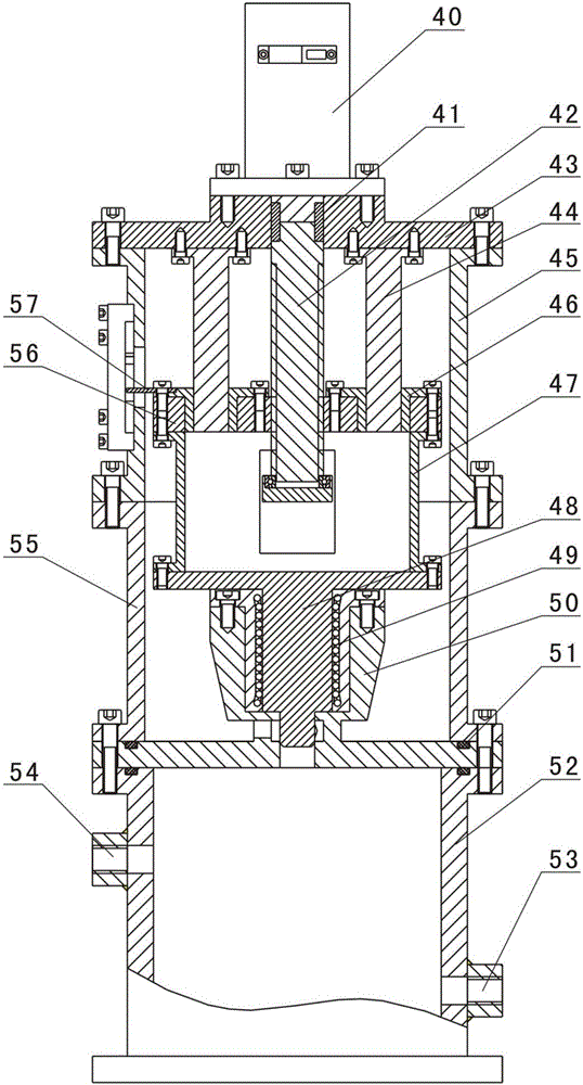
[0056] Such as Figure 3-Figure 20 As shown, the oil supply hydraulic adjustment device for the piston cooling nozzle performance test bench of the present invention includes a stepper motor 40, a round key 41, a screw 42, a thrust plate 64, a deep groove ball bearing 63, Guide rod 44, top plate 43, support cylinder 45, moving plate 56, copper sliding sleeve 46, follower cylinder 47, moving shaft 48, oil retaining cylinder 55, oil return pipe 66, linear bearing 49, bearing seat 50, auxiliary oil tank 52, auxiliary oil tank The oil inlet 54 on the top of the 52 is connected to the oil outlet of the oil supply source (not shown in the figure), and the oil outlet 53 on the lower part of the auxiliary oil tank 52 is connected to the piston cooling nozzle (see Figure 22 , Figure 23 The oil inlet of the piston cooling nozzle 114) is connected, the bottom plate of the bearing ...


PUM


Abstract

The invention discloses an oil supply hydraulic adjusting device for a piston cooling nozzle performance experiment bench. The oil supply hydraulic adjusting device comprises a stepping motor, a lead screw, a top plate, a supporting cylinder, a moving plate, a follow-up cylinder, a moving shaft, an oil blocking cylinder, an oil returning pipe, a linear bearing, a bearing pedestal and an auxiliary oil tank; the auxiliary oil tank is connected with an oil supply source and a piston cooling nozzle, and the bearing pedestal is mounted on the auxiliary oil tank and provided with an oil drainage groove and an oil drainage hole; the moving shaft can vertically move to change the oil drainage amount in the oil drainage groove; the moving shaft is sequentially driven by the follow-up cylinder and the moving plate, and the moving plate is connected with and driven by a rotating shaft of the stepping motor through the lead screw; the stepping motor is adopted to drive the lead screw to rotate, and then drives the moving shaft to vertically move, the oil drainage groove and the oil drainage hole formed in the bearing pedestal are blocked through the moving shaft, the magnitude of the oil drainage output of the oil drainage groove and the oil drainage hole is changed, bypass throttling pressure adjustment can be formed, and therefore the aim of adjusting output pressure is achieved; and running of the device cannot cause temperature rise of detection medium engine oil, and use is easy and convenient.

Description

technical field [0001] The invention relates to an accessory of a performance test bench of a piston cooling nozzle, in particular to an oil supply hydraulic adjustment device used for a performance test bench of a piston cooling nozzle. Background technique [0002] Piston cooling nozzle (ie PCN) is an important part of the automobile engine, and its performance has an extremely important effect on the lubrication and cooling effect of the moving piston of the engine; the test curve of the piston cooling nozzle performance experiment is as follows figure 1 shown. [0003] The piston cooling nozzle is composed of a nozzle body and a one-way valve. Based on the diversity of automobile engine specifications and models, there are many specifications and models of piston cooling nozzles, but their structural forms are roughly similar. [0004] The switch characteristics and flow characteristics tests of the piston cooling nozzles are factory inspection items, which require 100%...

Claims


Application Information

Patent Timeline
IPC IPC(8): F15B19/00
CPCF15B19/005
Inventor 李代生邓红梅王军王莹汤海泓杜寿兵
Owner GENERAL ENG RES INST CHINA ACAD OF ENG PHYSICS
Why Eureka
Try Eureka