Multifunctional hydraulic combination valve

A hydraulic combined valve and multi-functional technology, applied in the field of hydraulic valves, can solve the problems of high manufacturing cost, multiple auxiliary components, complex structure of the unloading solenoid valve, etc., achieve convenient manufacturing and processing, meet the needs of system work, and ensure normal work. Effects of Temperature and Reliability

Inactive Publication Date: 2016-08-10
GUIZHOU UNIV
View PDF12 Cites 1 Cited by
  • Summary
  • Abstract
  • Description
  • Claims
  • Application Information

AI Technical Summary

Problems solved by technology

The structure of the unloading solenoid valve is complicated, the manufacturing cost is high, and more auxiliary components are required. In addition, this method requires a corresponding circuit control device to control the solenoid valve

Method used


Image

  • Multifunctional hydraulic combination valve
  • Multifunctional hydraulic combination valve
  • Multifunctional hydraulic combination valve

Examples


Embodiment Construction

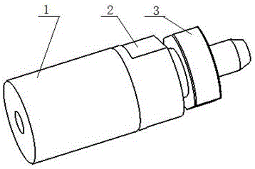
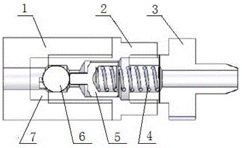
[0030] Embodiment of the present invention: a multi-functional hydraulic combination valve, as shown in the accompanying drawings, includes a valve seat 1, an oil drain screw 3 is installed on the right side of the valve sleeve 2 through a threaded connection, and the valve sleeve 2 is installed on the valve seat through a threaded connection 1 on the right side, a steel ball installation hole 8 is set on the left side of the valve sleeve 2, and a valve seat step shaft hole 9 is set on the right side of the valve seat 1, and the steel ball seat 7 is installed in the valve seat step shaft hole 9 and the steel ball The seat 7 is aligned with the steel ball mounting hole 8, the steel ball 6 is placed in the steel ball mounting hole 8 and can move in the steel ball mounting hole 8 and the steel ball seat 7, the core rod 5 is installed in the middle of the valve sleeve 2 and the core The ejector rod 10 of the rod 5 corresponds to the steel ball 6, the spring 4 is installed inside th...


PUM


Abstract

The invention discloses a multifunctional hydraulic combination valve which comprises a valve seat. An oil leakage screw is installed on the right side of a valve sleeve in a threaded connection mode. The valve sleeve is installed on the right side of the valve seat in a threaded connection mode. A steel ball mounting hole is formed in the left side inside the valve sleeve. A valve seat stepped shaft hole is formed in the right side inside the valve seat. A steel ball seat is installed in the valve seat stepped shaft hole and aligned at the steel ball mounting hole. A steel ball is installed in the steel ball mounting hole and can move in the steel ball mounting hole and the steel ball seat. A mandrel is installed in the middle portion inside the valve sleeve, and an ejector rod of the mandrel corresponds to the steel ball. A spring is installed in the connecting position of the valve sleeve and the oil leakage screw. The front end of the spring abuts against the mandrel, and the rear end of the spring abuts against the oil leakage screw. The multifunctional hydraulic combination valve is simple in structure, convenient to manufacture and machine, and high in response frequency.

Description

technical field [0001] The invention relates to the technical field of hydraulic valves, in particular to a multifunctional hydraulic combined valve. Background technique [0002] The existing unloading overflow valve is composed of an overflow valve and a check valve. When the system pressure reaches the opening pressure of the relief valve, the relief valve opens for unloading; when the system pressure drops to the closing pressure of the relief valve, the relief valve closes and the system continues to load. The unloading relief valve unloads the oil in the system when the pressure reaches a certain value. At present, there is no valve that can prevent air from entering the system when the system oil pressure is lower than the atmospheric pressure, prevent oil leakage before the system oil pressure exceeds the atmospheric pressure, and cut off the oil when the set pressure is reached. . [0003] The hydraulic oil in the hydraulic system is used as the transmission medi...

Claims


Application Information

Patent Timeline
Patent Type & Authority Applications(China)
IPC IPC(8): F16K1/14F16K17/06F16K27/02F15B13/02
CPCF15B13/02F16K1/14F16K17/0406F16K17/0466F16K17/06F16K27/0245
Inventor 陈家兑吴中义张超王自勤田丰果
Owner GUIZHOU UNIV
Why Eureka
Try Eureka