
Gradient drying device for pine nuts

A drying device and gradient technology, applied in the field of pine nut gradient drying device, can solve the problems of poor drying effect and low drying efficiency, and achieve the effect of avoiding mildew and overheating

Inactive Publication Date: 2016-08-10
张立新
View PDF8 Cites 4 Cited by
  • Summary
  • Abstract
  • Description
  • Claims
  • Application Information

AI Technical Summary

Problems solved by technology

[0003] The purpose of the present invention is to provide a gradient drying device for pine nuts, which fundamentally solves the problems of poor drying effect and low drying efficiency of existing drying devices. inferior merit

Method used


Image

  • Gradient drying device for pine nuts
  • Gradient drying device for pine nuts
  • Gradient drying device for pine nuts

Examples


Embodiment 1

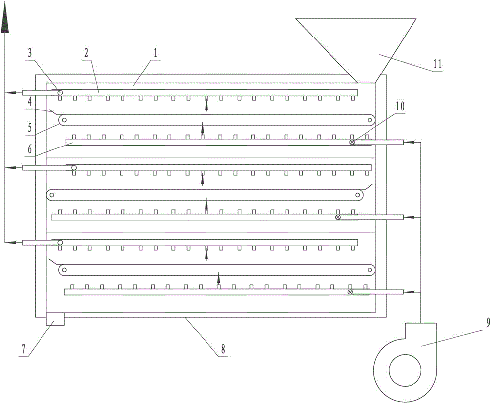
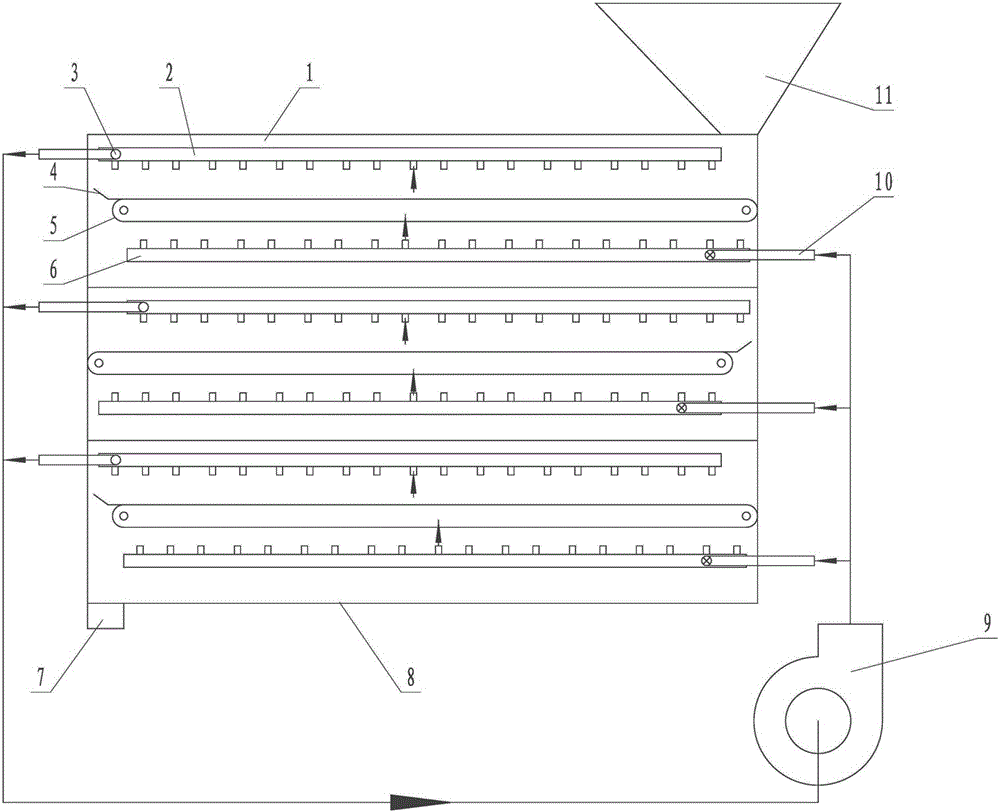
[0020] The pine nut gradient drying device includes a thermal insulation shell 8 arranged on a horizontal plane, a fan 9, and three sequentially connected drying units 1 arranged vertically from top to bottom, which are arranged in the thermal insulation casing and connected to the fan. A hopper 11 is provided on the drying unit at the front end, and a discharge port 7 is provided at the bottom of the drying unit at the end. The drying unit includes a drying shell, a conveyor belt 5 made of metal mesh arranged in the drying shell, an exhaust main pipe 2 arranged above the conveyor belt, and an air inlet main pipe 6 arranged below the conveyor belt. The end of each conveyor belt is provided with an upturned baffle plate 4, and there is a gap of a certain width between the baffle plate and the inner wall of the housing of the drying unit. The lower drying unit falls into the lower drying unit when being squeezed by pine nuts, so as to avoid hindering the movement of pine nuts. ...

Embodiment 2

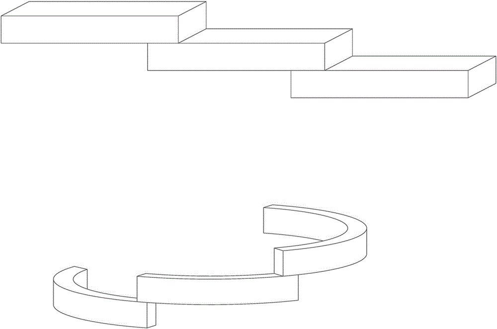
[0022] The combined layout of each drying unit is not unique. In addition to the vertical layout of Embodiment 1, in order to meet the needs of the actual site, the following can also be used: Figure 4 The ladder shape and ring shape are shown, but the floor space of the ladder shape layout is too large, the material consumption of each unit shell is large, and the insulation effect is poor, which is not conducive to saving manufacturing and use costs, so it is usually not used. Although the ring layout occupies a smaller area than the stepped layout, it is not usually used.

[0023] The conveyor belt in each technical solution of the present invention can be a belt with a through hole, or a metal mesh can be used directly. Since metal has a better heat conduction effect and is more conducive to drying, the metal mesh is preferred.

[0024] The thermal insulation shells in the various technical solutions of the present invention can be respectively arranged outside each dryin...


PUM


Abstract

A gradient drying device for pine nuts comprises a fan and more than two drying units connected to the fan. The gradient drying device is technically characterized in that the drying units are sequentially connected and sequentially arranged from top to bottom; each drying unit comprises a conveyor belt which is arranged in a drying shell and provided with ventilation holes; an exhaust main pipe is arranged above each conveyor belt, an air inlet main pipe is arranged below each conveyor belt, a plurality of pipe openings are formed between the exhaust main pipe or / and the air inlet main pipe and the conveyor belt, an air outlet connected with the fan or led to the shell outer part of each drying unit is arranged on each exhaust main pipe, and an air inlet connected with the fan is arranged on each air inlet main pipe; and the hole diameters of the air inlet or / and the air outlet is sequentially reduced from top to bottom. The problems of the existing drying device, such as poor drying effect and low drying efficiency, are radically solved. The gradient drying device has the advantages of being simple and compact in structure, convenient and rapid in use, low in manufacture and use cost and the like.

Description

technical field [0001] The invention relates to dried fruit drying equipment, in particular to a gradient drying device for pine nuts. Background technique [0002] Existing drying equipment, such as "a staggered multi-layer drying chamber" disclosed in the invention patent application with the application publication number CN105486041A, includes a drying chamber body, a partition, a drying furnace and a screen plate. The partition is set in the drying chamber body, its upper end is connected with the top of the drying chamber body, and there is a gap between the lower end and the bottom of the drying chamber body; the screen is horizontally arranged in the drying chamber body on the left side of the partition, and the screen There are multiple layers, and the stencil apertures of the multi-layers gradually increase from top to bottom. The drying furnace is located on the right side of the partition, and it includes a furnace door, a furnace body, a combustion chamber, hea...

Claims


Application Information

Patent Timeline
Patent Type & Authority Applications(China)
IPC IPC(8): F26B17/04F26B23/10F26B25/02
CPCF26B17/04F26B23/10F26B25/02F26B2200/06
Inventor 张立新张宝宝
Owner 张立新
Learn More