Fiber grating type pressure transducer for rock-soil complete stress measurement

A technology of pressure sensor and optical fiber grating, which is applied in the field of geotechnical engineering measurement, can solve the problems of cumbersome embedding, difficulty in measuring the stress state, and inability to measure the stress state of the rock mass.

Active Publication Date: 2016-08-10
INST OF ROCK & SOIL MECHANICS CHINESE ACAD OF SCI +2
View PDF6 Cites 15 Cited by
  • Summary
  • Abstract
  • Description
  • Claims
  • Application Information

AI Technical Summary

Problems solved by technology

Obviously, this method is not only cumbersome to bury, but also difficult to measure the stress state at the same point due to the scattered arrangement of earth pressure cells
For rock mass stress measurement, most commonly used rigid inclusion stress gauges can only measure one-way or two-way stress changes perpendicular to the drilling plane, and cannot be used for rock mass stress state measurement

Method used


Image

  • Fiber grating type pressure transducer for rock-soil complete stress measurement
  • Fiber grating type pressure transducer for rock-soil complete stress measurement
  • Fiber grating type pressure transducer for rock-soil complete stress measurement

Examples


Embodiment 1

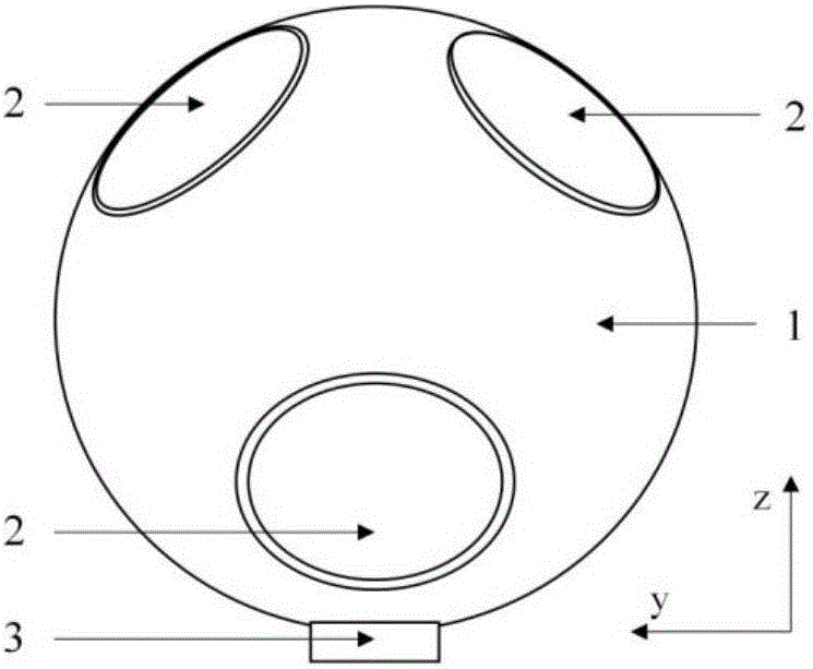
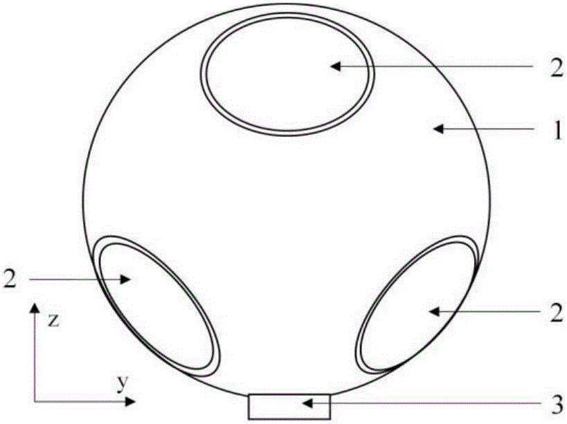
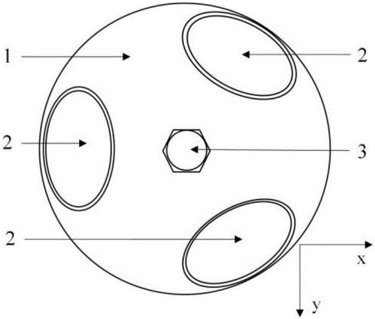
[0049] A fiber grating type pressure sensor for rock and soil complete stress measurement, comprising a spherical shell 1, the upper half of the spherical shell 1 is provided with three cylindrical holes 1-1, and the lower half of the spherical shell 1 is provided with three A cylindrical hole 1-1, the centerline of each cylindrical hole 1-1 passes the center of the sphere of the spherical shell 1 and each cylindrical hole 1-1 communicates at the center of the sphere of the spherical shell 1, the cylindrical hole 1-1 1 includes mounting holes of the first diameter, mounting holes of the second diameter and mounting holes of the third diameter which decrease successively from the surface of the spherical shell 1 to the center of the sphere and which are concentric to the center line, and a bearing plate 2-1, The force transmission column 2-2 and the sensing film 2-3, the column 2-4 and the fiber grating strain gauge 2-5 are arranged in the installation hole of the second diamete...

Embodiment 2

[0053] Such as Figure 8-1~Figure 8-2 As shown, the angle between the normal direction of the three pressure sensing units in the upper half of the sphere 1 (ie the direction of the centerline of the cylindrical hole 1-1) and the horizontal plane is 45°, and the angle projected on the horizontal plane is 120°. The angle between the normal direction of the three pressure sensing units in the lower half (that is, the direction of the centerline of the cylindrical hole 1-1) and the horizontal plane is 30°, and the angle projected on the horizontal plane is also 120°. The included angle of the element normal projected on the horizontal plane is 60°. The cylindrical outlet hole 1-2 is perpendicular to the horizontal plane.

[0054] Others are the same as in Example 1.

[0055] According to the above-mentioned angular arrangement of the pressure sensing unit, the cosine value of the normal direction of the pressure sensing unit and the x-axis, y-axis and z-axis of the coordinate s...


PUM


Abstract

The invention discloses a fiber grating type pressure transducer for rock-soil complete stress measurement, comprising a spherical housing; each of the upper part and the lower part of the spherical housing is provided with three cylindrical holes; the cylindrical holes comprise a first diameter installation hole, a second diameter installation hole and a third diameter installation hole which are successively decreased from the surface of the spherical housing to the center of sphere; the first diameter installation hole is internally provided with a bearing plate, a stress transfer column and an induction film; the second diameter hole is internally provided with a vertical column and a fiber grating strainometer; and the third diameter installation hole is provided with an optical fiber. The fiber grating type pressure transducer can obtain the stress state of one point through a solving equation according to the measurement pressure of six pressure sensors. The fiber grating type pressure transducer is safe in usage, not interfered by the electromagnetism, can realize signal long distance transmission, and has characteristics of long term stability, large measurement range, high accuracy, pressure resistance, erosion resistance, etc.

Description

technical field [0001] The invention belongs to the field of geotechnical engineering measurement, in particular to an optical fiber grating type pressure sensor used for geotechnical complete stress measurement. Background technique [0002] In the field of geotechnical engineering, obtaining the stress state of soil or rock mass through stress measurement is one of the important conditions for engineering stability analysis and safety evaluation. [0003] At present, soil stress measurement is mainly realized by embedding earth pressure cells (or earth pressure gauges) in the soil. Most of the commonly used earth pressure cells are unidirectional pressure sensors, which can only measure the normal stress in a certain direction. According to the theory of elastic mechanics, the complete stress state of a point contains six independent stress components, which means that six earth pressure cells with different angles need to be buried to obtain the soil stress state. Obvio...

Claims


Application Information

Patent Timeline
Patent Type & Authority Applications(China)
IPC IPC(8): G01L1/24
CPCG01L1/246
Inventor 朱元广刘泉声康永水刘滨薛俊华余国峰
Owner INST OF ROCK & SOIL MECHANICS CHINESE ACAD OF SCI
Why Eureka
Try Eureka