Barn sample splitter

A sample divider and granary technology, applied in the preparation of test samples, etc., can solve the problems of deviation of test results, uneven distribution, easy to produce objective errors, etc., to reduce errors, avoid errors and intentional, and scientific sampling work. and rigorous effect

Active Publication Date: 2016-08-10
张兆军
View PDF13 Cites 2 Cited by
  • Summary
  • Abstract
  • Description
  • Claims
  • Application Information

AI Technical Summary

Problems solved by technology

[0002] In the grain, oil, and feed industry, after the grain, oil, and feed are stored in a fixed form, when new grain acceptance or old grain re-inspection is required, there are big problems in the process of mixing and dividing samples after comprehensive sampling. The bag-style quartering method is very easy to produce local deposition of impurities and uneven quality when mixing samples, and it is very inconvenient to operate. The direct flow pours out one after another, which often makes the distribution of impurities and broken corn grains uneven in the three or more samples taken. In some samples, the impurities may be 0.2 or 3%. The impurities in other samples sometimes reached 2.0%, which caused great deviations in the test results and was very unfavorable for the test work.
Second, in the above method of mixing and dividing samples, it is easy to produce subjective errors in addition to objective errors.
The third is that the workload of sample separation is heavy, and it takes up a lot of manpower and time, and the work efficiency is low. Therefore, it is urgent to develop a more scientific, more accurate, and more convenient granary sample separation instrument and promote its application to solve the confusion that the grain, oil and feed industry has many granaries. To solve the difficult problem of sampling and dividing samples, and promote the scientific development of the inspection work of the grain, oil and feed industry

Method used


Image

  • Barn sample splitter
  • Barn sample splitter
  • Barn sample splitter

Examples


Embodiment Construction

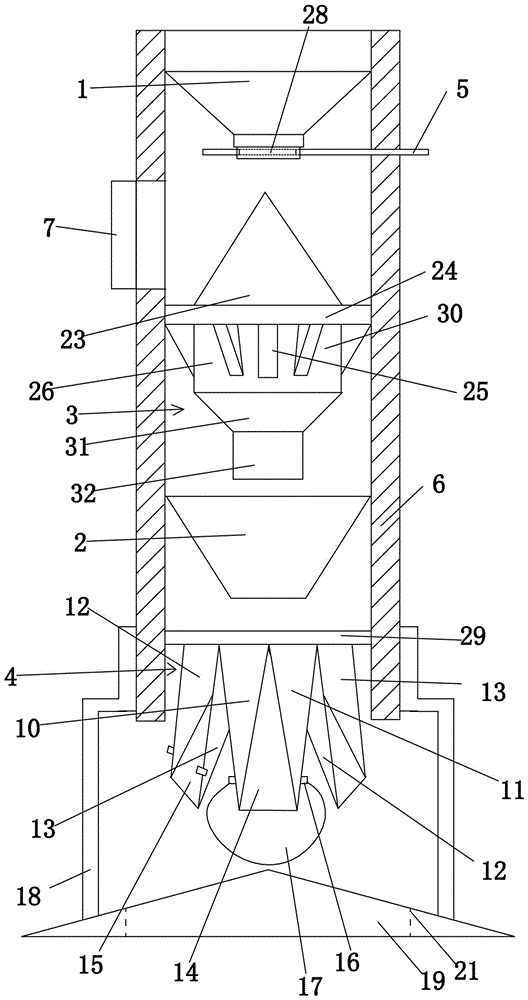
[0048] The granary sample divider includes a sample divider 6.

[0049] The sample dividing cylinder 6 includes a first funnel 1 , a first sample dividing body 3 , a second funnel 2 and a second sample dividing body 4 sequentially from top to bottom. The sample-dividing cylinder 6 is a cylindrical shape with upper and lower openings.

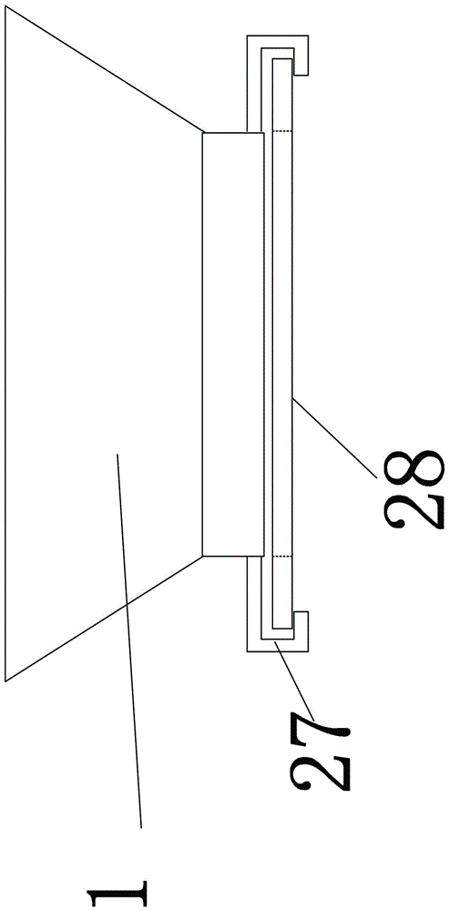
[0050] The outlet of the first funnel 1 is located above the tip of the first sample dividing body 3 .

[0051] The first sub-sample 3 is a Canadian sub-sample, which is a known technology.

[0052] The upper end of the first dividing body 3 is a conical casing 23, the lower end of the conical casing 23 is connected to the first cylindrical casing 26, and the lower end of the first cylindrical casing 26 is connected to the second cylinder through a frustum-shaped casing 31 Type shell 32. The diameter of the first cylindrical shell 26 is larger than that of the second cylindrical shell 32 .

[0053] The insides of the conical housing 23 , the...


PUM


Abstract

A barn sample splitter comprises a sample splitting cylinder. A first hopper, a first sample splitting body, a second hopper and a second sample splitting body are sequentially arranged in the sample splitting cylinder from top to bottom. The outlet of the first hopper is located above the first sample splitting body. The lower outlet of the first sample splitting body is located above the center of the second hopper. The outlet of the second hopper is located above the center of the second sample splitting body. The second sample splitting body comprises a supporting ring. A plurality of ribs are arranged in the supporting ring in the radius direction. Two openings formed by every three adjacent ribs form a set of sample splitting openings including the main opening and the auxiliary opening which are arranged in an adjacent and separated mode. A first slide groove is arranged below each main opening, and a second slide groove is arranged below each auxiliary opening. When taken through different sample taking devices, corresponding reasonable amounts of samples can be freely and respectively taken through the different outlets of the sample splitter by means of the sample splitter during sample splitting.

Description

technical field [0001] The invention belongs to the field of grain, oil and feed inspection instruments, in particular to a granary sample divider. Background technique [0002] In the grain, oil, and feed industry, after the grain, oil, and feed are stored in a fixed form, when new grain acceptance or old grain re-inspection is required, there are big problems in the process of mixing and dividing samples after comprehensive sampling. The bag-style quartering method is very easy to produce local deposition of impurities and uneven quality when mixing samples, and it is very inconvenient to operate. The direct flow pours out one after another, which often makes the distribution of impurities and broken corn grains uneven in the three or more samples taken. In some samples, the impurities may be 0.2 or 3%. The impurities in other samples sometimes reached 2.0% or so, which caused great deviations in the test results and was very unfavorable for the test work. Second, in add...

Claims


Application Information

Patent Timeline
Patent Type & Authority Applications(China)
IPC IPC(8): G01N1/38
CPCG01N1/38
Inventor 张兆军
Owner 张兆军
Why Eureka
Try Eureka