Rotor structure for improving permanent magnet motor power and torque density

A technology of torque density and rotor structure, applied in the field of special motors, to achieve the effect of improving utilization, improving power and torque density, and simplifying design procedures

Inactive Publication Date: 2016-08-10
SOUTHEAST UNIV
View PDF6 Cites 5 Cited by
  • Summary
  • Abstract
  • Description
  • Claims
  • Application Information

AI Technical Summary

Problems solved by technology

Due to the shortage of rare earth permanent magnet resources, the manufacturing cost of permanent magnet motors has become a bottleneck for the large-scale application of permanent magnet motors

Method used


Image

  • Rotor structure for improving permanent magnet motor power and torque density
  • Rotor structure for improving permanent magnet motor power and torque density
  • Rotor structure for improving permanent magnet motor power and torque density

Examples


Embodiment 1

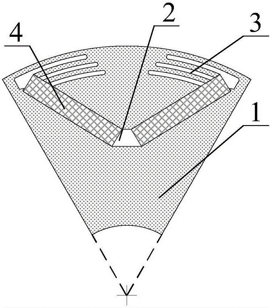
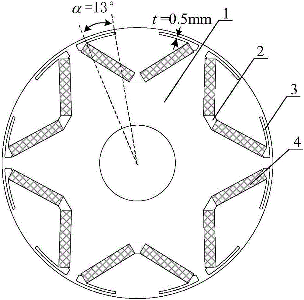
[0021] Such as figure 2 As shown, this embodiment has a structure of 6 poles and 9 slots, and adopts a centralized winding structure. The left and right tops of the permanent magnet slots 2 of the rotor 1 are each provided with a symmetrical bar-shaped slot 3 . The width of the strip groove 3 is t=0.5mm, and the angle α=13°.

Embodiment 2

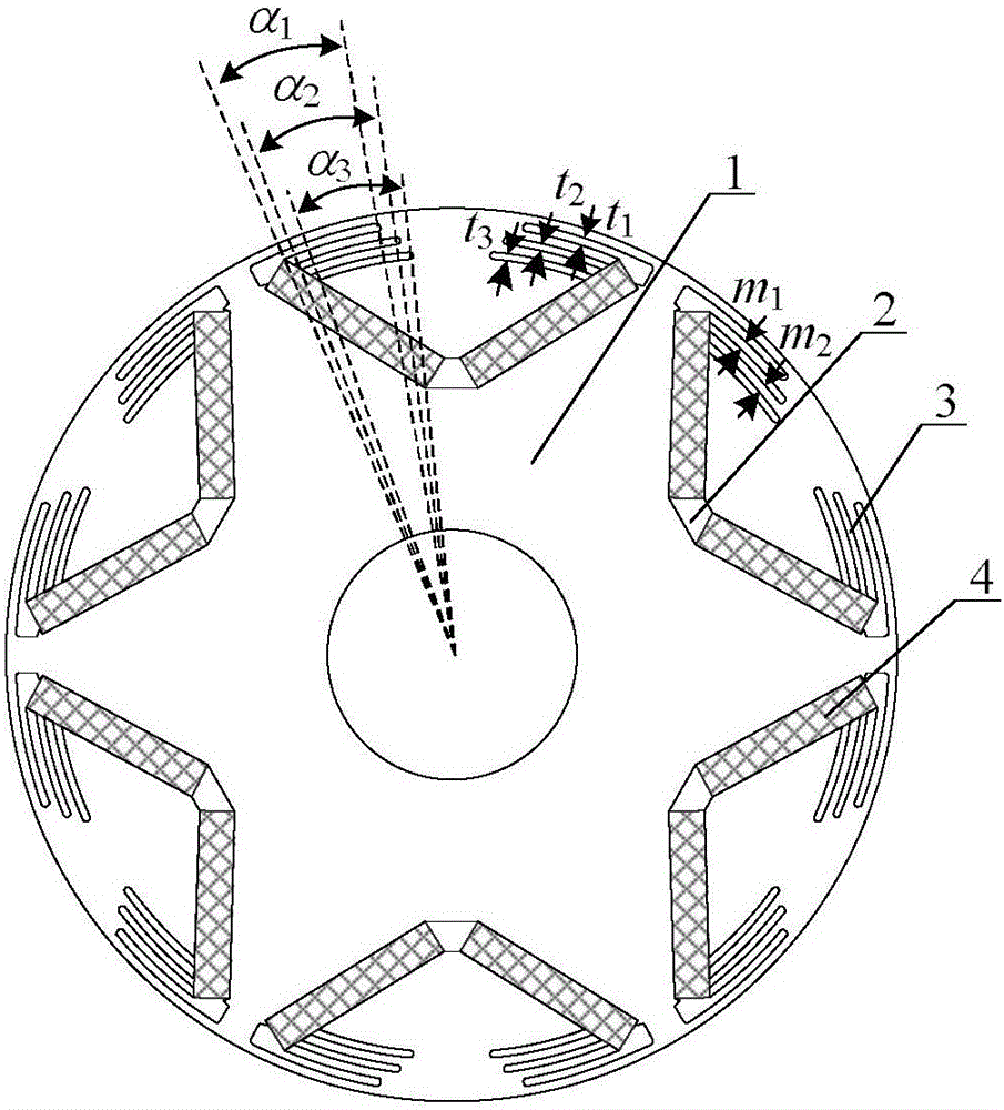
[0023] Such as image 3 As shown, this embodiment has a structure of 6 poles and 18 slots, and adopts a distributed winding structure. The left and right tops of the permanent magnet slots 2 of the rotor 1 are respectively provided with three symmetrical bar-shaped slots 3 . The width t of the strip groove 3 1 = t 2 = t 3 = 0.8mm, angle α 1 = α 2 = α 3 = 8°.

Embodiment 3

[0025] Such as Figure 4 As shown, this embodiment has a structure of 8 poles and 12 slots, and adopts a centralized winding structure. Two symmetrical bar-shaped slots 3 are respectively opened on the left and right tops of the permanent magnet slots 2 of the rotor 1 . Described strip groove 3 width t=0.6mm, angle α 1 = 5°, α 2 =7°.


PUM


Abstract

The invention discloses a rotor structure for improving permanent magnet motor power and torque density. The rotor is obtained through laminating silicon steel sheets. The rotor is provided with a trough for embedding a permanent magnet. The trough for embedding the permanent magnet is a V-shaped trough which faces the outer circle of the rotor. The left top end and the right top end of the V-shaped trough is provided with a plurality of symmetrical elongated troughs which are communicated with the V-shaped trough. Compared with the rotor structure of an existing permanent magnet motor, the rotor structure has advantages of improving a magnetic flux path through arranging the elongated troughs, reducing magnetic leakage, improving utilization rate of the permanent magnet, adding a saliency effect, improving efficiency and power density of the motor, reducing cogging torque, simplifying a motor optimization program and improving design efficiency.

Description

technical field [0001] The invention relates to a permanent magnet motor rotor structure, especially a built-in permanent magnet motor rotor structure, which is suitable for applications where the volume, weight, power and torque of the motor are limited (such as compressors, air-conditioning fans, electric motors, etc.) Tools and electric vehicles, etc.), which belong to the field of special motor technology. Background technique [0002] Permanent magnet motors have remarkable characteristics such as high power density, high efficiency, and high reliability, and have been widely used in the fields of production and life. Due to the shortage of rare earth permanent magnet resources, the manufacturing cost of permanent magnet motors has become a bottleneck for the large-scale application of permanent magnet motors. Therefore, the optimal design of the permanent magnet motor structure and the improvement of its power and torque density have become a research topic for expert...

Claims


Application Information

Patent Timeline
Patent Type & Authority Applications(China)
IPC IPC(8): H02K21/14H02K1/26H02K1/27
CPCH02K21/14H02K1/265H02K1/276H02K2201/03H02K2213/03
Inventor 林明耀徐磊
Owner SOUTHEAST UNIV
Why Eureka
Try Eureka