

Production equipment of push-and-pull cables
A technology of production equipment and push-pull cables, which is applied in the field of production equipment of push-pull cables, can solve problems such as high labor costs, low production efficiency, and inaccurate manual positioning, and achieve the effect of high degree of automation and good consistency of production batches
- Summary
- Abstract
- Description
- Claims
- Application Information
AI Technical Summary
Problems solved by technology
Method used
Image

Examples
Embodiment Construction
[0026] Below will combine in the embodiment of the present invention Attached picture , clearly and completely describe the technical solutions in the embodiments of the present invention, obviously, the described embodiments are only some of the embodiments of the present invention, not all of them. All other embodiments obtained by persons of ordinary skill in the art based on the embodiments of the present invention belong to the protection scope of the present invention.
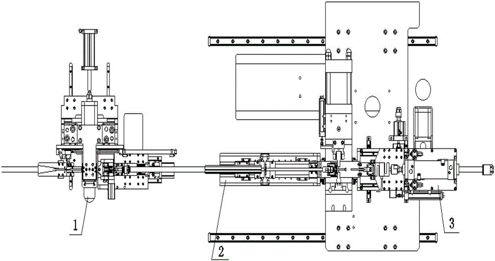
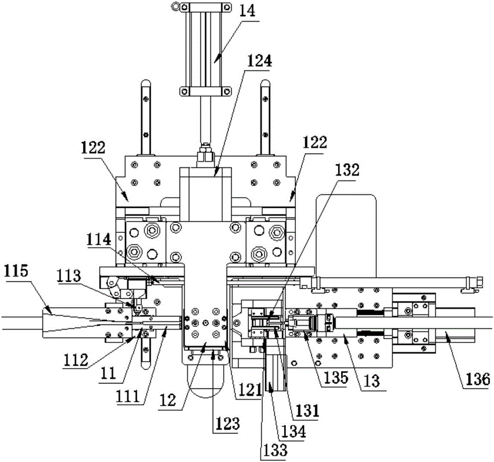
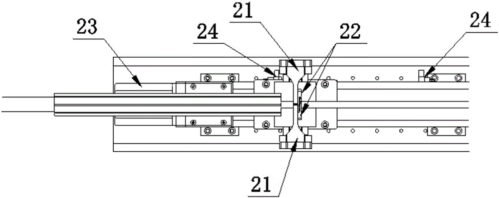
[0027] as shown in the picture 1-4 As shown, according to the embodiment of the present invention A kind of production equipment of push-pull cable , including an oiled threading device 1, a star-shaped sheath positioning device 2 and a joint rod riveting device 3, and the oil-coated threading device 1, the star-shaped sheath positioning device 2 and the joint rod riveting device 3 are sequentially arranged from left to right connect;
[0028] The oiled threading device 1 includes a steel wire rope...
PUM
 Abstract
Description
Claims
Application Information