A mechanical processing device for convenient adjustment of clearance

A technology for gap adjustment and mechanical processing, which is applied in the direction of mechanical equipment, transmission devices, metal processing equipment, etc., can solve the problems of push-pull driving accuracy, complex workload, heavy processing head weight, etc., to avoid dimensional changes and ensure accurate driving performance, reliable operation

Active Publication Date: 2018-04-17
安徽全浩铝材有限公司
View PDF5 Cites 0 Cited by
  • Summary
  • Abstract
  • Description
  • Claims
  • Application Information

AI Technical Summary

Problems solved by technology

This method is easy to cause the processing head to be too heavy
However, although the push-pull drive with rollers does not need to apply the weight of the drive system to the processing head when performing the auxiliary drive, the gap between the rollers and the processing head often affects the accuracy of the push-pull drive.
Adjusting the gap often brings complicated workload

Method used


Image

  • A mechanical processing device for convenient adjustment of clearance
  • A mechanical processing device for convenient adjustment of clearance
  • A mechanical processing device for convenient adjustment of clearance

Examples


Embodiment Construction

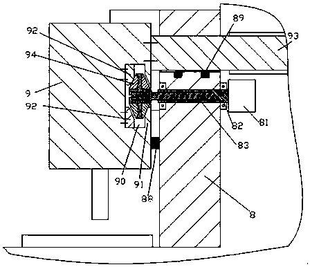
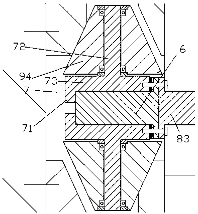
[0009] Combine below Figure 1-3 The present invention will be described in detail.

[0010] According to an embodiment of the present invention, a machining device for convenient gap adjustment includes a frame 8 and a processing head 9 mounted on the frame 8 in a reciprocating manner in the front-rear direction, and the processing head 9 is provided with There is a chute cavity 90 extending in the front-rear direction, and the chute cavity 90 is used to roll and cooperate with the roller pushing device so as to be pushed and pulled by the roller pushing device to adjust the position of the processing head 9 perpendicular to the front-rear direction. The position on the left-right direction, wherein the roller pusher includes a threaded sleeve part 82 rotatably installed on the frame 8 for threaded engagement with a threaded moving rod 83, and the threaded sleeve part 82 is driven by a drive motor 81 is driven to rotate, and the threaded moving rod 83 is detachably fixedly c...


PUM


Abstract

A machining device with clearance convenient to regulate comprises a rack (8) and a machining head (9) which is installed on the rack (8) in a reciprocating motion mode in the front-back direction. The machining head (9) is internally provided with a sliding groove cavity (90) extending in the front-back direction. The sliding groove cavity (90) is used for being in rolling fit with an idler wheel thrust unit so that the machining head can be pushed and pulled by the idler wheel thrust unit and the position of the machining head can be regulated in the left-right direction orthogonal to the front-back direction. The idler wheel thrust unit comprises a threaded sleeve part (82) rotationally installed on the rack (8) and used for being in threaded fit with a threaded shifting bar (83).

Description

technical field [0001] The invention relates to the field of processing devices, in particular to a mechanical processing device for convenient gap adjustment. Background technique [0002] There is a wide range of needs for back-and-forth and lateral drives of machine heads. In some existing devices, orthogonal drive systems are often superimposed on each other, that is, one drive is the main drive, and the other auxiliary drive is located within the main drive. This way is easy to cause the processing head to be too heavy. However, although the push-pull drive of the rollers can be used to implement the auxiliary drive, the weight of the drive system need not be applied to the processing head, but the gap between the rollers and the processing head often affects the precision of the push-pull drive. Adjusting the gap often brings complicated workload. Contents of the invention [0003] The object of the present invention is to provide a machining device for convenient...

Claims


Application Information

Patent Timeline
Patent Type & Authority Patents(China)
IPC IPC(8): B23Q1/25F16H25/20
CPCB23Q1/25F16H25/20
Inventor 范全有
Owner 安徽全浩铝材有限公司
Why Eureka
Try Eureka