Disassembly and assembly tool for optical fiber connectors

A fiber optic connector and tooling technology, which is applied in the direction of manufacturing tools and hand-held tools, can solve the problem of insufficient clamping and positioning stability and disassembly force stability, low efficiency of fiber optic connector disassembly work, and affecting the processing quality of fiber optic connectors, etc. problems, to achieve the effect of improving positioning stability and reliability, improving disassembly efficiency, and positioning stability

Active Publication Date: 2016-08-17
SUZHOU JIALAN ZHIYUAN ELECTRONICS TECH CO LTD
View PDF6 Cites 2 Cited by
  • Summary
  • Abstract
  • Description
  • Claims
  • Application Information

AI Technical Summary

Problems solved by technology

[0002] At present, in the actual production and operation process, it is often necessary to disassemble the assembled optical fiber connector or the optical fiber connector with quality problems. However, due to the small size and smooth surface of the optical fiber connector, it is difficult to The disassembly of optical fiber connectors requires the use of special disassembly tools, but in actual use, it is found that the current disassembly equipment for optical fiber connectors often lacks flexibility in use, and the stability of clamping positioning and clamping force and disassembly force are limited. The stability is insufficient, so on the one hand, the disassembly work efficiency of the optical fiber connector is low, and on the other hand, it also causes the surface of the optical fiber connector to be easily scratched or squeezed during disassembly, which seriously affects the performance of the optical fiber connector. Processing quality, that is, the tightening and fixing devices currently used for fixing products are easy to tighten the surface of the product, causing scratches, resulting in product scrapping, and the product requires no scratches

Method used


Image

  • Disassembly and assembly tool for optical fiber connectors

Examples


Embodiment Construction

[0013] In order to make the technical means, creative features, goals and effects achieved by the present invention easy to understand, the present invention will be further described below in conjunction with specific embodiments.

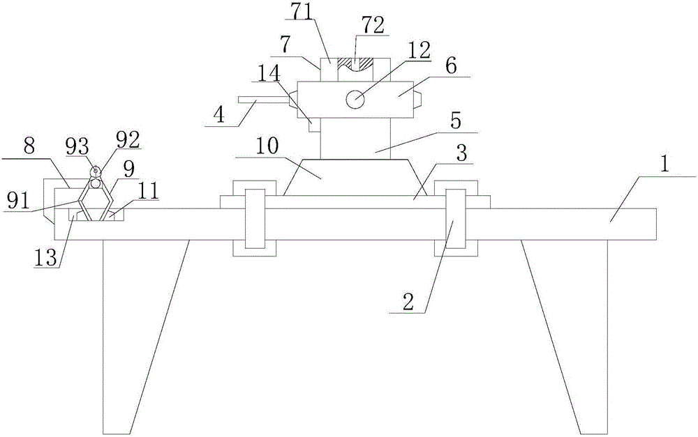
[0014] Such as figure 1 The disassembly and assembly tooling for the optical fiber connector includes a workbench 1, a positioning buckle 2, a positioning base 3, a driving rod 4, a driving screw 5, a driving screw sleeve 6, a chuck 7, a connecting belt 8 and a dismounting pliers 9 , the workbench 1 is distributed parallel to the horizontal, the positioning base 3 is installed on the upper surface of the workbench 1 and connected with the workbench 1 through the positioning buckle 2, at least two positioning buckles 2 are symmetrically distributed on the axis of the positioning base 3, and the positioning base 3 is on the Connecting screw holes 10 are provided on the end surface, and are connected to the driving screw 5 through the connecting scre...


PUM


Abstract

The invention relates to a disassembly and assembly tool for optical fiber connectors. The disassembly and assembly tool comprises a base, at least one vertical column, a cross beam, a detector and a detection terminal; at least four adjusting bolts are arranged on the lower surface of the base, and a detection platform is arranged on the upper surface of the base; the tail end of the vertical column is perpendicularly connected to the edge position of the upper surface of the base; the tail end of the cross beam is arranged outside the vertical column in a sleeving mode and is connected to the vertical column in a sliding mode, the front end of the cross beam is hinged to the detector through a locating pin, and the cross beam comprises a rod body, a connecting ratchet wheel and an organ type protection cover; the detection terminal is installed right below the detector, is connected to the detector and comprises a test end, a fixed threaded sleeve, a ceramic locating rod and a test head, wherein the top end of the test end is connected to the detector, and the tail end of the test end is connected to the top end of the fixed threaded sleeve. According to the disassembly and assembly tool, the work efficiency and the work quality of the focal distance detection work of the optical fiber connectors can be improved effectively, the replacement efficiency of parts of detection equipment can be improved effectively, the service life of the parts of the detection equipment can be prolonged effectively, and the detection cost can be lowered.

Description

technical field [0001] The invention relates to a dismantling device for an optical fiber connector, in particular to a dismantling tool for an optical fiber connector. Background technique [0002] At present, in the actual production and operation process, it is often necessary to disassemble the assembled optical fiber connector or the optical fiber connector with quality problems. However, due to the small size and smooth surface of the optical fiber connector, it is difficult to The disassembly of optical fiber connectors requires the use of special disassembly tools, but in actual use, it is found that the current disassembly equipment for optical fiber connectors often lacks flexibility in use, and the stability of clamping positioning and clamping force and disassembly force are limited. The stability is insufficient, so on the one hand, the disassembly work efficiency of the optical fiber connector is low, and on the other hand, it also causes the surface of the opt...

Claims


Application Information

Patent Timeline
Patent Type & Authority Applications(China)
IPC IPC(8): B25B27/02
CPCB25B27/02
Inventor 毕延文余新文孙兴元
Owner SUZHOU JIALAN ZHIYUAN ELECTRONICS TECH CO LTD
Why Eureka
Try Eureka