A mold device

A mold and template technology, applied in the field of mold devices, can solve the problems of lower precision, increased cost, damage to the upper mold barrel, etc., and achieve the effects of reducing wear, reducing maintenance costs, and reducing friction

Active Publication Date: 2018-08-10
CHONGQING QILONG IND & TRADE CO LTD
View PDF6 Cites 0 Cited by
  • Summary
  • Abstract
  • Description
  • Claims
  • Application Information

AI Technical Summary

Problems solved by technology

[0002] The upper mold barrel of the traditional mold device is a smooth cylinder. When the upper mold barrel moves up and down in the hole of the lower mold barrel, if the center of gravity of the upper mold barrel deviates, the outer wall of the upper mold barrel and the inner side of the lower mold barrel will There is strong friction between the walls. If it is used for a long time, it will reduce the precision of the products produced on the one hand, and damage the upper mold barrel on the other hand. Maintenance or replacement of the upper mold barrel will increase the cost

Method used


Image

  • A mold device

Examples


Embodiment Construction

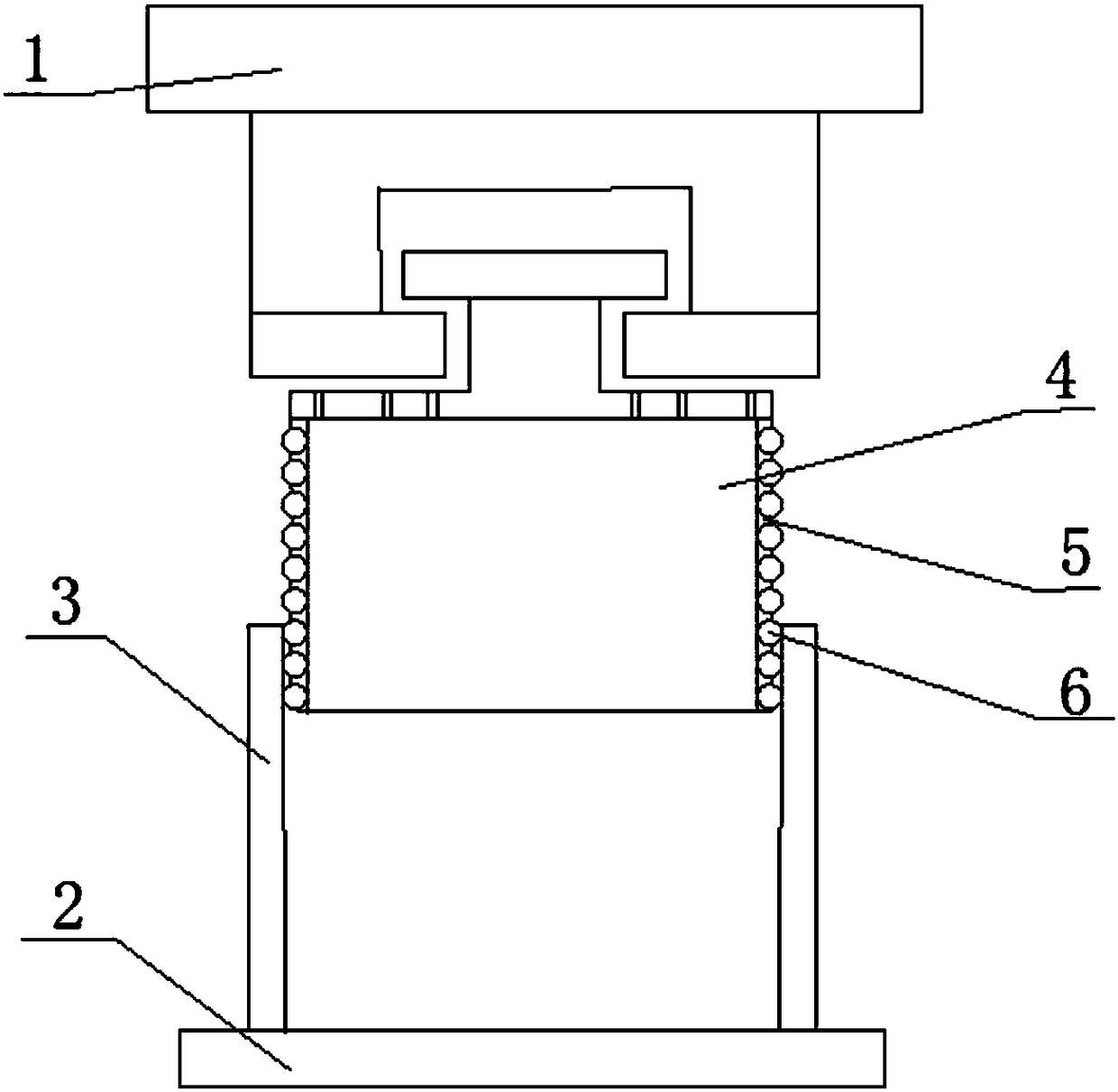
[0021] As mentioned in the background technology section, the upper mold barrel of the current mold device is not only easy to wear, but also very inconvenient to replace the upper mold barrel.

[0022] On the basis of the above research, the embodiment of the present invention provides a mold device. Through the multiple balls arranged on the side wall of the copper sleeve, when the upper mold barrel slides in the lower mold barrel, the outer side of the upper mold barrel can be avoided. The wall and the inner side wall of the lower mold barrel cause severe friction due to direct contact, and at the same time, because the ball can roll in the second through hole on the copper sleeve, the friction between the steel ball and the upper mold barrel and the lower mold barrel can be reduced, thereby reducing the friction of the upper mold. Wear of barrel and die barrel. When the balls are greatly worn, remove the copper sleeve from the upper mold barrel, then replace the balls and ...


PUM

PropertyMeasurementUnit
diameteraaaaaaaaaa

Abstract

The invention discloses a mould device. The mould device comprises an upper mould plate and a lower mould plate, and further comprises a lower mould cylinder, an upper mould cylinder and a copper sleeve, wherein the lower mould cylinder is fixedly connected with the lower mould plate; a first through hole is formed in the middle of the lower mould cylinder; the upper mould cylinder is fixedly connected with the upper mould plate and can slide in the first through hole; the copper sleeve detachably sleeves the outer side wall of the upper mould cylinder; a plurality of second through holes of which the axes are perpendicular to the axis of the copper sleeve are formed in the side wall of the copper sleeve; balls capable of rolling in the second through holes are arranged in all the second through holes; and the diameter of each ball is greater than the thickness of the side wall of the copper sleeve. The mould device provided by the invention has the advantages that when the upper mould cylinder slides in the lower mould cylinder, the friction between the balls, namely steel balls, and the upper mould cylinder, the friction between the steel balls and the lower mould cylinder, as well as the friction between the upper mould cylinder and the lower mould cylinder can be reduced because a plurality of the balls capable of rolling are arranged on the side wall of the copper sleeve; and when relatively serious abrasion is caused by the balls, only the balls need to be replaced, that is, the upper mould cylinder needs not be replaced, so that the maintenance efficiency is improved and the maintenance cost is reduced.

Description

technical field [0001] The invention relates to the technical field of mechanical equipment, in particular to a mold device. Background technique [0002] The upper mold barrel of the traditional mold device is a smooth cylinder. When the upper mold barrel moves up and down in the hole of the lower mold barrel, if the center of gravity of the upper mold barrel deviates, the outer wall of the upper mold barrel and the inner side of the lower mold barrel will There is strong friction between the walls. If it is used for a long time, it will reduce the precision of the products produced on the one hand, and damage the upper mold barrel on the other hand. Maintenance or replacement of the upper mold barrel will increase the cost. [0003] Therefore, how to reduce the wear of the upper mold barrel, and then reduce the maintenance cost of the mold device, is a technical problem that those skilled in the art urgently need to solve. Contents of the invention [0004] The purpose ...

Claims


Application Information

Patent Timeline
Patent Type & Authority Patents(China)
IPC IPC(8): B30B15/02
CPCB30B15/02
Inventor 曾庆华
Owner CHONGQING QILONG IND & TRADE CO LTD
Why Eureka
Try Eureka