Automatic drawing-penetrating shaft and adapting structure of winding machine

A technology for adapting structures and winding machines, which is applied in the directions of coiling strips, thin material processing, transportation and packaging, etc., can solve the problems that equipment cannot be automatically adapted, cannot meet production needs, and has a low degree of automation. Simple and reasonable, easy to realize, low work intensity effect

Active Publication Date: 2016-08-17
佛山市顺德区捷勒塑料设备有限公司
View PDF8 Cites 9 Cited by
  • Summary
  • Abstract
  • Description
  • Claims
  • Application Information

AI Technical Summary

Problems solved by technology

However, the degree of automation is extremely low, relying entirely on the operator to manually adjust the center height of the plastic film roll, the operation is complicated and time-consuming
Moreover, three-inch and six-inch diameters are the two most commonly used winding shaft specifications in the processing process of the winding machine. Under the traditional design concept, the diameter specification of the winding shaft needs to be determined at the beginning of the equipment design, or a smaller diameter should be used. 3-inch paper core, or a 6-inch paper core with a larger diameter, the 3-inch and 6-inch diameter winding shafts must be manually switched and adjusted by personnel during each processing, and the equipment cannot be automatically adapted, resulting in production efficiency Low, unable to meet production needs

Method used


Image

  • Automatic drawing-penetrating shaft and adapting structure of winding machine
  • Automatic drawing-penetrating shaft and adapting structure of winding machine
  • Automatic drawing-penetrating shaft and adapting structure of winding machine

Examples


Embodiment Construction

[0018] The present invention will be further described below in conjunction with the accompanying drawings and embodiments.

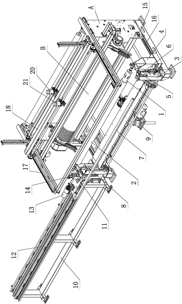
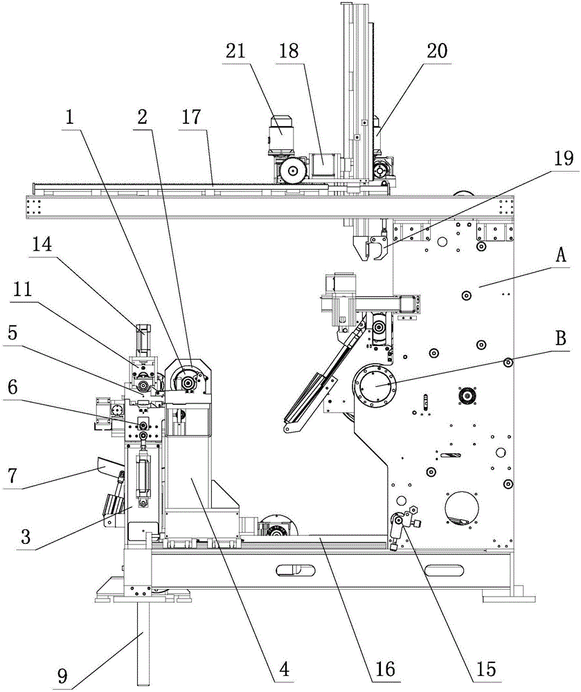
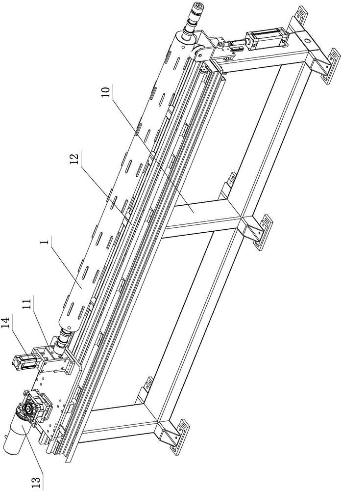
[0019] see Figure 1-Figure 3 , the automatic pull-through shaft and the matching structure of the winder include the main body A of the winder, and the main body A of the winder is provided with an air expansion shaft 1, a winding shaft 2, a winding device B, a conveying device, and an air expansion shaft Threading and pumping device, tray bracket 3 and winding trolley 4; the winding shaft 2 is sleeved on the inflatable shaft 1 at least when rolling the film, and the two move between the winding trolley 4 and the tray bracket 3 through the conveying device; Among them, the tray bracket 3 is provided with a proximity switch 5 and a limit switch 6. The air shaft 1 is automatically pulled away from the winding shaft 2 through the cooperation of the air shaft threading device and the proximity switch 5. The cooperation of the shaft threading device and th...


PUM


Abstract

The invention relates to an automatic drawing-penetrating shaft and adapting structure of a winding machine. The structure comprises a winding machine body, wherein a gas expansion shaft, a winding shaft, a winding device, a conveying device, a gas expansion shaft drawing-penetrating device, a tray bracket and a winding trolley are arranged on the winding machine body; the winding shaft at least sleeves the gas expansion shaft when a film is wound, and the winding shaft and the gas expansion shaft are movably arranged between the winding trolley and the tray bracket through the conveying device; a proximity switch and a limiting switch are arranged on the tray bracket; and the gas expansion shaft and the winding shaft are mutually and automatically separated through the cooperation between the gas expansion shaft drawing-penetrating device and the proximity switch and are mutually and automatically penetrated through the cooperation between the gas expansion shaft drawing-penetrating device and the limiting switch. By virtue of the structural improvement, the automatic drawing-penetrating shaft and adapting structure has the characteristics of simplicity and reasonability, excellent performance, convenience in operation, high production efficiency, low manufacturing cost, easiness in production and realization, safety, reliability and the like, can be widely applied to large, small and medium-size industrial production and is strong in practicability.

Description

technical field [0001] The invention relates to a winder, in particular to an automatic draw-through shaft and an adaptation structure of the winder. Background technique [0002] The paper core (or plastic core) of the traditional winding machine must be threaded and drawn manually. The labor intensity of the operation is high, the time for threading and drawing the shaft is long, and there is a certain risk. Someone has designed an electric shaft threading and shaft extraction device, which is driven by a motor to complete the shaft threading and shaft extraction actions, which reduces the labor intensity of workers and eliminates the danger of the shaft threading and shaft extraction process. However, the degree of automation is extremely low, relying entirely on the operator to manually adjust the center height of the plastic film roll, the operation is complicated and time-consuming. Moreover, three-inch and six-inch diameters are the two most commonly used winding sha...

Claims


Application Information

Patent Timeline
Patent Type & Authority Applications(China)
IPC IPC(8): B65H19/30
CPCB65H19/30B65H19/305
Inventor 彭坚
Owner 佛山市顺德区捷勒塑料设备有限公司
Why Eureka
Try Eureka