
A kind of igniter for discharging jet

An igniter and jet-releasing technology, which is applied in the directions of combustion ignition, ignition through the guide flare, combustion method, etc., can solve the problems of low ignition reliability, poor safety, inconvenient installation, etc., and achieve safe and reliable ignition, safe and reliable ignition, Strong flame effect

Active Publication Date: 2018-08-21
CHINA PETROLEUM & CHEM CORP +1
View PDF5 Cites 0 Cited by
  • Summary
  • Abstract
  • Description
  • Claims
  • Application Information

AI Technical Summary

Problems solved by technology

[0003] The purpose of the present invention is to provide an igniter for releasing jets, which solves the problems of low ignition reliability, inconvenient installation, and poor safety in the prior art, so that the flame rigidity is strong and the ignition is safe and reliable.

Method used


Image

  • A kind of igniter for discharging jet
  • A kind of igniter for discharging jet
  • A kind of igniter for discharging jet

Examples


Embodiment

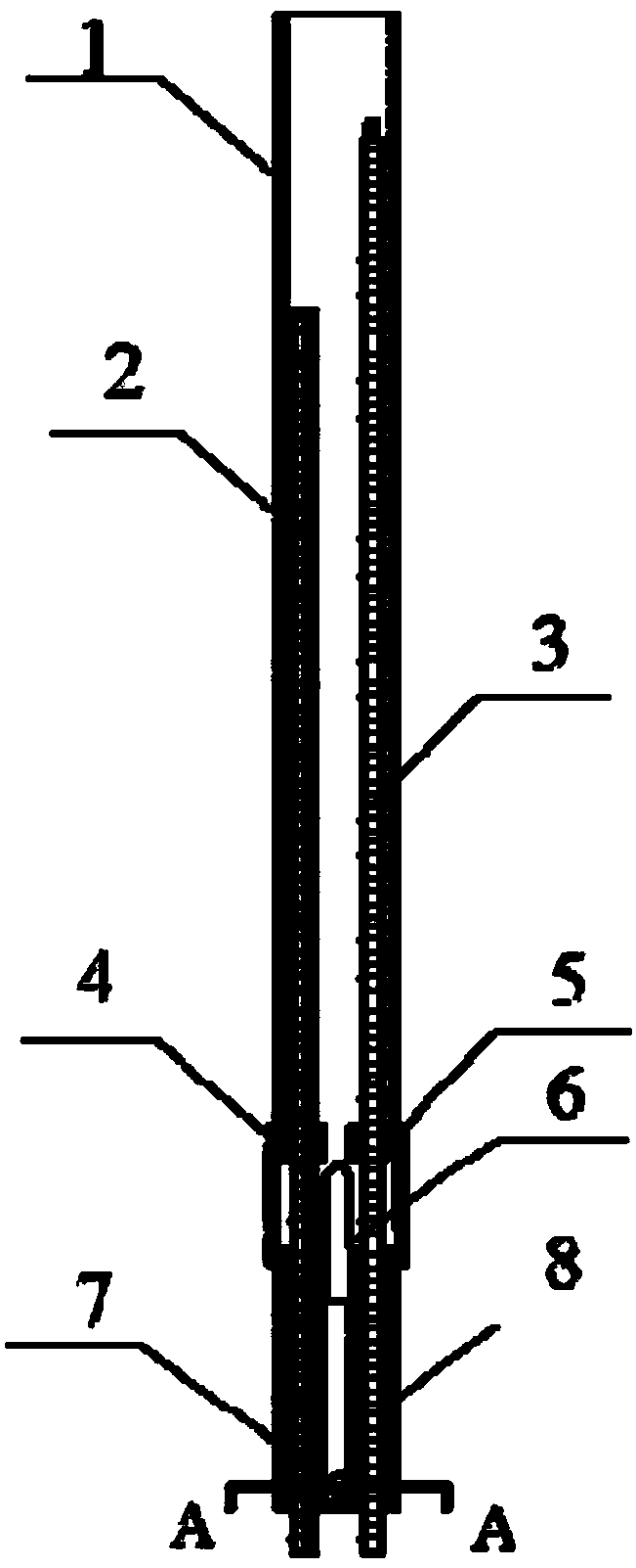
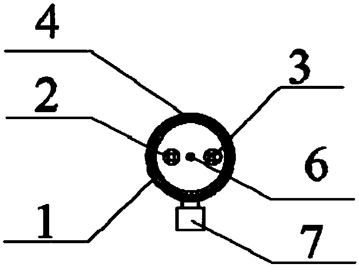
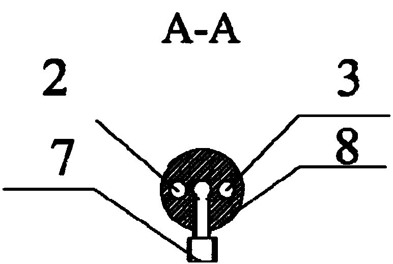
[0019] An igniter for blowing gas, such as Figure 1 to Figure 3 As shown, a combustion tube 1 is included, an ignition needle 2 and a flame probe 3 are arranged in the combustion tube 1, the combustion tube 1 is connected with a burner joint 8, and a nozzle 6 is provided on the burner joint 8. The bottom of the combustion tube 1 is provided with a fuel gas inlet 7 .

[0020] In the above embodiments, the combustion cylinder 1 is provided with a limiting hole 5 .

[0021] In the above embodiments, the combustion cylinder 1 is connected to the burner joint 8 through the connecting rod 4 .

[0022] In the above embodiments, the fuel gas inlet 7 is connected to the intake pipeline of liquefied petroleum gas or atomized diesel gas.

[0023] In the above embodiments, the fuel gas inlet 7 is connected to the liquefied petroleum gas or atomized diesel gas inlet pipe through threads or flanges.

[0024] In the above embodiments, the burner joint 8 is provided with a fuel flow chann...


PUM


Abstract

The invention relates to an igniter used for deflation and gas injection. The igniter comprises a combustion cylinder. An ignition needle and a flame probe are arranged in the combustion cylinder. The combustion cylinder is connected with a combustor connector. The combustor connector is provided with a nozzle. A fuel gas inlet is formed in the bottom of the combustion cylinder. By means of the igniter, liquefied petroleum gas or atomized diesel oil serves as fuel, an automatic ignition function and a flame monitoring function are achieved, and the igniter is used for achieving safe and reliable ignition in the deflation and injection process during shale gas testing. The problems that in the prior art, ignition reliability is low, installation is not convenient, and safety performance is poor can be solved. The flame rigidity of the igniter is high, ignition is safe and reliable, a real-time flame monitoring function is achieved, and safe and reliable ignition can be achieved during shale gas deflation and injection.

Description

technical field [0001] The invention belongs to the technical field of ignition for jetting, and in particular relates to an igniter for jetting. Background technique [0002] At present, there are mainly four kinds of gas ignition technologies for test gas blowing: (1) oil drum ignition: the burner is ignited by setting a small oil drum above the burner, or pulling a small oil drum by a steel wire rope, but due to the The material pressure is huge, and the burning small iron drum will be overturned when it is close to the injected material, and the fuel may be extinguished in an instant under the strong pressure of the injection, and the second ignition cannot be approached when the first ignition is unsuccessful. (2) Ignition by ignition device: From the structure, it can be divided into orbital mobile type and fixed type. From the principle of ignition, it can be divided into high-pressure ignition and high-energy ignition. From the source of ignition gas, it can be divid...

Claims


Application Information

Patent Timeline
Patent Type & Authority Patents(China)
IPC IPC(8): F23Q9/00
CPCF23Q9/00
Inventor 张杰东于安峰王鹏党文义韩中枢
Owner CHINA PETROLEUM & CHEM CORP
Learn More