
Method for improving vibration monitoring precision of rotor aeroengine

An aero-engine and vibration monitoring technology, which is applied in the direction of engine testing, machine/structural component testing, measuring devices, etc., can solve problems such as large measurement errors

Active Publication Date: 2016-08-17
NORTHWESTERN POLYTECHNICAL UNIV
View PDF7 Cites 5 Cited by
  • Summary
  • Abstract
  • Description
  • Claims
  • Application Information

AI Technical Summary

Problems solved by technology

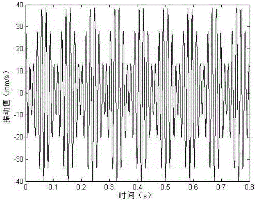
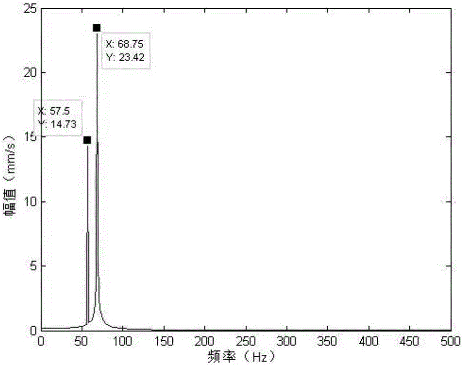
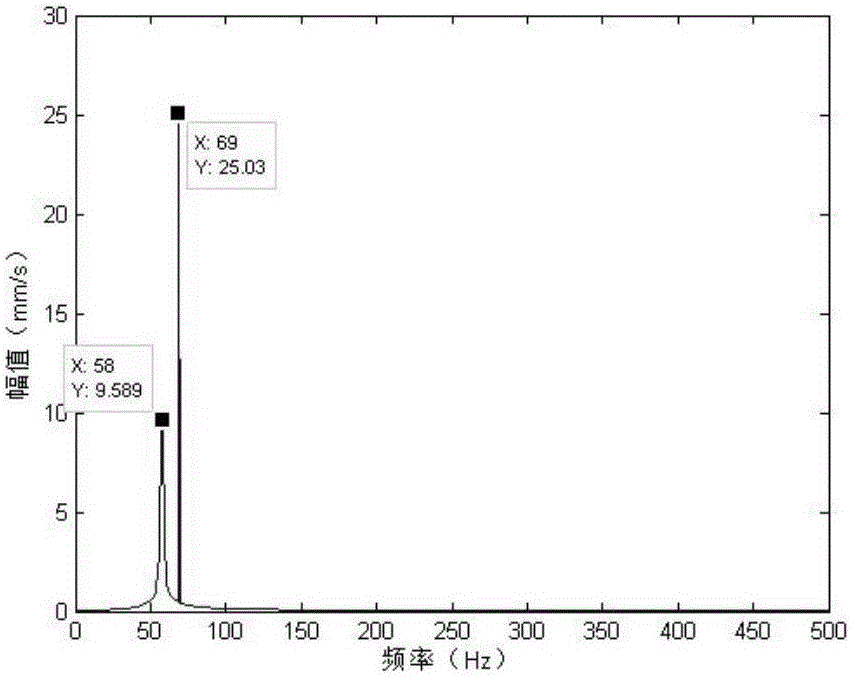
[0008] In order to overcome the large error in simultaneous measurement of the high-voltage fundamental frequency amplitude and low-pressure fundamental frequency amplitude of aero-engines in the prior art, the present invention proposes a method for improving the vibration monitoring accuracy of multi-rotor aero-engines

Method used


Image

  • Method for improving vibration monitoring precision of rotor aeroengine
  • Method for improving vibration monitoring precision of rotor aeroengine
  • Method for improving vibration monitoring precision of rotor aeroengine

Examples


Embodiment 1

[0057] This embodiment is a method for improving the vibration monitoring accuracy of a dual-rotor aeroengine, and the specific process is:

[0058] Step 1, collect the rotational speed of each rotor of the engine. Acquisition based on onboard sensor signals.

[0059] For a dual-rotor engine, the high-pressure rotor speed n of the engine is collected at the same time 2 and low pressure rotor speed n 1 .

[0060] Step 2: Determine the sampling frequency of the vibration signal according to the structural parameters of the engine.

[0061] According to formula (1), the sampling frequency f of the vibration signal is determined by two parameters, namely the reference rotor rotation frequency f 0 and the number of sampling points per cycle 2 Z .

[0062] Among them, the reference rotor rotation frequency f 0 Determined by formula (2):

[0063] f=2 Z f 0 (1)

[0064] The reference rotor selects the rotor with the highest rotational speed among the rotors of the engine. ...

Embodiment 2

[0090] This embodiment is a method for improving the vibration monitoring accuracy of a three-rotor aero-engine, and the specific process is:

[0091] Step 1, collect the rotational speed of each rotor of the engine. Acquisition based on onboard sensor signals.

[0092] For a three-rotor engine, the high-pressure rotor speed n of the engine is collected at the same time 3 , Medium pressure rotor speed n 2 and low pressure rotor speed n 1 . The unit of each rotor speed is rev / min.

[0093] Step 2: Determine the sampling frequency of the vibration signal according to the structural parameters of the engine.

[0094] According to formula (1), the sampling frequency f of the vibration signal is determined by two parameters, namely the reference rotor rotation frequency f 0 and the number of sampling points per cycle 2 Z .

[0095] f=2 Z f 0 (1)

[0096] The reference rotor selects the rotor with the highest rotational speed among the rotors of the engine. Using equati...


PUM


Abstract

The invention provides a method for improving the vibration monitoring precision of a rotor aeroengine, and the method employs a calculated sampling frequency for the continuous collection of a signal, wherein the collection length is a calculated period number, thereby achieving a purpose of the full-period collection of two or three fundamental frequencies, so as to guarantee the precision of the subsequent data processing. The method employs a dynamic optimization sampling rate and collection point number method, tries to avoid the frequency spectrum leakage of the fundamental frequencies of all rotors at the same time, and improves the amplitude testing precision. Therefore, the method can increase the effective information amount in a vibration signal, and provides technological basis for reducing the number of airborne sensors. The method can remarkably reduce collection precision of the fundamental frequencies of all rotors, guarantees the normal operation of an engine, provides the technological basis for the fault diagnosis of the engine and the onsite dynamic balance, and provides technological support for the health management of the engine.

Description

technical field [0001] The invention relates to the technical field of aero-engine fault diagnosis and health management, in particular to a method for improving the measurement accuracy of the fundamental frequency amplitude of a multi-rotor aero-engine rotor. Background technique [0002] More and more aero-engine models use the rotor fundamental frequency amplitude as a characteristic parameter to measure the vibration of the whole engine. The rotor fundamental frequency amplitude monitoring method can not only effectively distinguish the vibration source, but also be a measure index of engine rotor unbalance. In CN201310227304.7 Engine Vibration and Engine Adjustment and Balance Test System, Equipment and Method, Boeing proposed the test system and equipment design for engine vibration and engine site dynamic balance. Accurately monitoring the amplitude of the fundamental frequency of the aeroengine rotor has become the primary task of engine fault diagnosis and health ...

Claims


Application Information

Patent Timeline
IPC IPC(8): G01M15/00G01H17/00
CPCG01H17/00G01M15/00
Inventor 王俨剀廖明夫张铮王鑫李斌王菲
Owner NORTHWESTERN POLYTECHNICAL UNIV
Learn More