
Method of adjusting virtual image projection distance and angle on binocular head-mounted device

A head-mounted device and projection distance technology, applied in optical components, optics, instruments, etc., can solve the problems of difficult control of precision, low degree of environmental fusion, and uncalculated depth information, etc., to achieve the effect of adjusting the virtual image angle

Inactive Publication Date: 2016-08-17
CHENGDU IDEALSEE TECH
View PDF6 Cites 7 Cited by
  • Summary
  • Abstract
  • Description
  • Claims
  • Application Information

AI Technical Summary

Problems solved by technology

Head-mounted display devices are the best application environment for Augmented Reality Technology (AR for short), which can present virtual information in the real environment through the head-mounted device window. However, most existing AR head-mounted display devices currently have Information superposition only considers the correlation with the X and Y axis coordinates of the target position, but does not calculate the depth information of the target, making the virtual information float in front of the human eye, the degree of integration with the environment is not high, and the user experience is not good
[0003] In the prior art, there are also methods for adjusting the depth of field on the head-mounted device. Most of them use mechanical methods to adjust the optical structure of the optical lens group, thereby changing the image distance of the optical original, and then realizing the adjustment of the depth of field of the virtual image. This method makes the head-mounted device Large volume, high cost and difficult to control precision

Method used


Image

  • Method of adjusting virtual image projection distance and angle on binocular head-mounted device
  • Method of adjusting virtual image projection distance and angle on binocular head-mounted device
  • Method of adjusting virtual image projection distance and angle on binocular head-mounted device

Examples


Embodiment Construction

[0024] The following will clearly and completely describe the technical solutions in the embodiments of the present invention with reference to the accompanying drawings in the embodiments of the present invention. Obviously, the described embodiments are only some, not all, embodiments of the present invention. Based on the embodiments of the present invention, all other embodiments obtained by persons of ordinary skill in the art without creative efforts fall within the protection scope of the present invention.

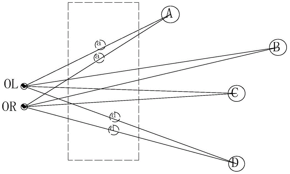
[0025] The inventors of the present invention have found that: when human eyes look at objects in different spatial positions, the viewing angles of the left and right eyes are different, such as figure 1 A / B / C / D in the middle represent targets in different orientations in space. When we look at target A, the sight directions of the left and right eyes are the space vectors where OLA / ORA are located. Similarly, in the field of augmented reality head-mounted devices...


PUM


Abstract

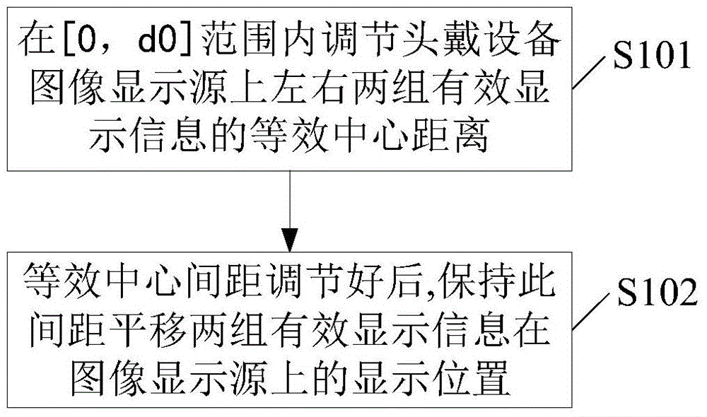
The invention discloses a method of adjusting a virtual image projection distance and / or a virtual image projection angle on a binocular head-mounted device. Through adjusting an equivalent center distance of a left group and a right group of effective display information on a head-mounted device image display source, the virtual image projection distance is adjusted; and through translating to change the display positions of the left group and the right group of effective display information on the image display source, the virtual image projection angle is adjusted. The traditional field depth adjustment starts from charging the optical original image distance, the traditional thinking is broken, the optical device structure is not changed, the field depth adjustment is realized through adjusting the equivalent center distance of the left group and the right group of effective display information on the image display source, creativity is realized, and compared with the method of changing the optical focal length, the practicability is realized. In addition, the traditional method of changing the field depth in a focal length adjusting mode, adjustment on a virtual image angle can not be realized. Through adjusting the display positions of the left group and the right group of effective display information, adjustment on the virtual image angle can be realized, and creativity is realized.

Description

technical field [0001] The invention relates to the field of head-mounted display devices, in particular to a method for adjusting the projection distance and angle of a virtual image on a binocular head-mounted device. Background technique [0002] With the rise of wearable devices, various head-mounted display devices have become the research and development hotspots of major giant companies, gradually entering people's field of vision. Head-mounted display devices are the best application environment for Augmented Reality Technology (AR for short), which can present virtual information in the real environment through the head-mounted device window. However, most existing AR head-mounted display devices currently have Information superposition only considers the correlation with the X and Y axis coordinates of the target position, but does not calculate the depth information of the target, so that the virtual information floats in front of the human eye, the degree of inte...

Claims


Application Information

Patent Timeline
Patent Type & Authority Applications(China)
IPC IPC(8): G02B27/01
Inventor 黄琴华李薪宇宋海涛
Owner CHENGDU IDEALSEE TECH
Learn More