Pressure release condensation heat transfer system for passive nuclear power station

A condensing heat transfer, passive technology, applied in nuclear power generation, nuclear engineering, cooling devices, etc., can solve the problems of reducing the natural circulation cooling flow of the reactor core, increasing the pressure of the containment, and reducing the liquid level in the pit, etc. Risk of radioactive leakage, effect of reducing back pressure and reducing load

Active Publication Date: 2016-07-27
STATE NUCLEAR HUAQING BEIJING NUCLEAR POWER TECH R & D CENT +1
View PDF5 Cites 13 Cited by
  • Summary
  • Abstract
  • Description
  • Claims
  • Application Information

AI Technical Summary

Problems solved by technology

This will lead to the following problems: 1) The pressure inside the containment vessel will increase, which in turn will affect the pressure relief of the main circuit system and delay the start of the gravity injection of the main make-up water tank into the reactor pressure vessel. At this time, the first make-up water tank and the second make-up water tank The make-up water tank is basically emptied, and the reactor core is in the dangerous period when the liquid level is the lowest in the accident, and the delay of pressure relief at this time increases the risk of reactor core exposure
According to the test and analysis of the existing technology (see the literature published in "Nuclear Engineering and Design" in 1999, the author is David E. Bessette, MarinodiMarzo and the name is "Transition from depression to long term cooling in AP600 scaled integral test facilities"), the main automatic pressure relief valve is opened and the main water tank is safely injected During this transition period between start-ups, the lowest liquid level in the reactor core will occur, so for the existing passive safety technology, the depressurization process of the main loop system after the main

Method used


Image

  • Pressure release condensation heat transfer system for passive nuclear power station
  • Pressure release condensation heat transfer system for passive nuclear power station
  • Pressure release condensation heat transfer system for passive nuclear power station

Examples


Embodiment Construction

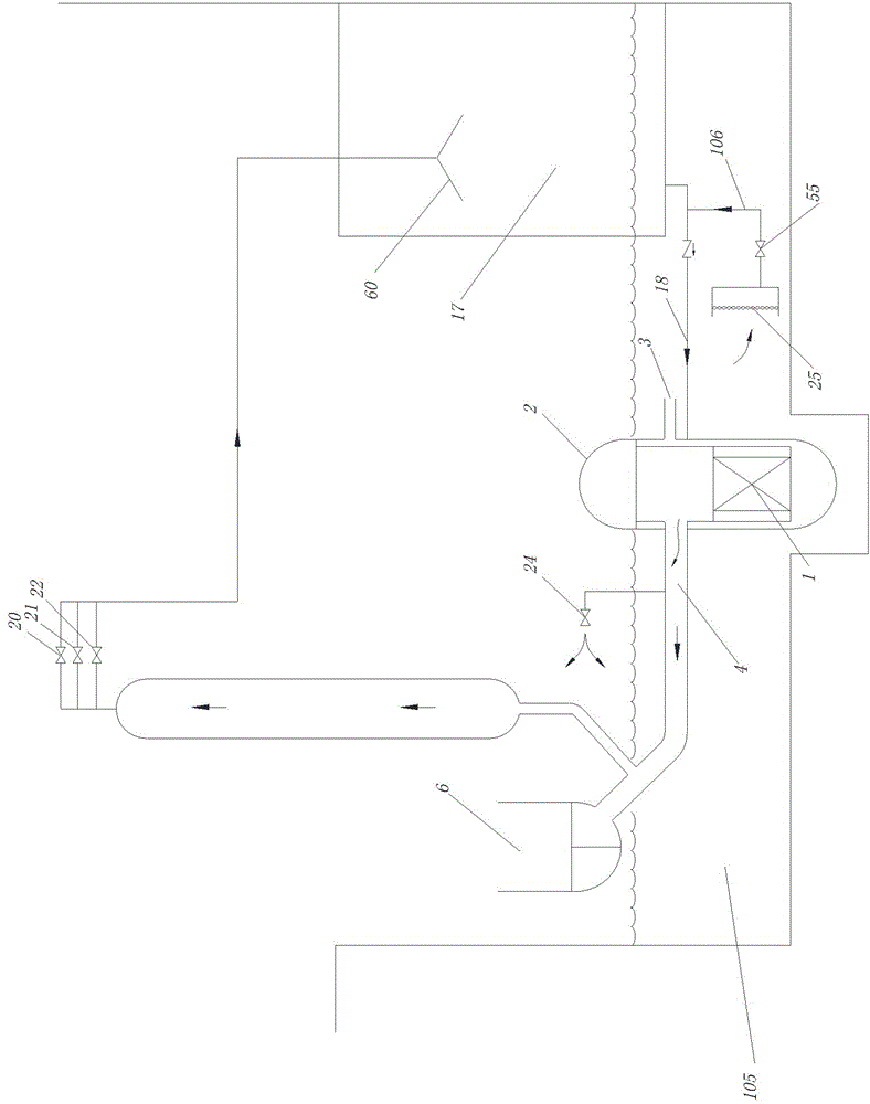
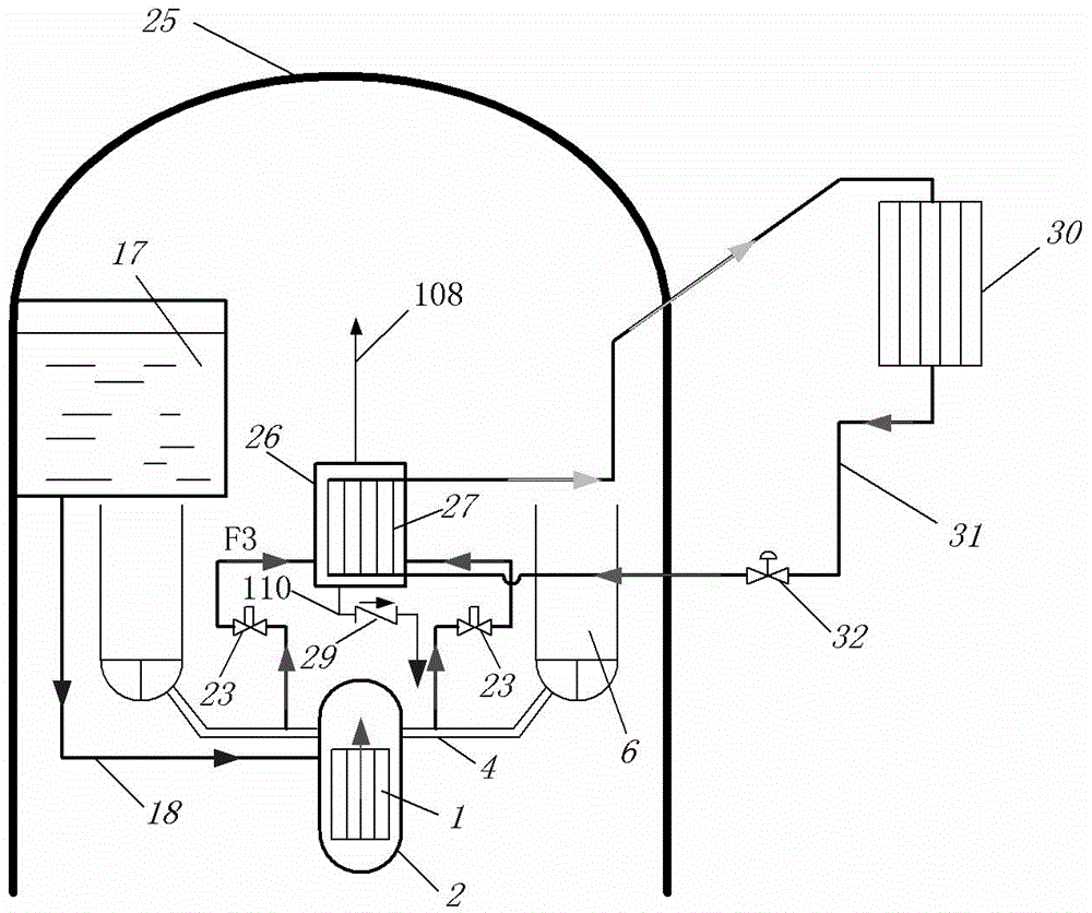
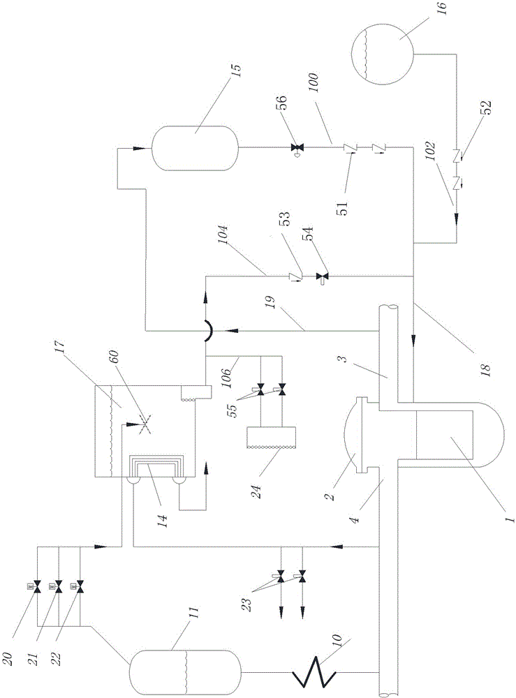
[0022] Figure 1-Figure 5 and the following description describe alternative embodiments of the invention to teach those of ordinary skill in the art how to make and reproduce the invention. In order to teach the technical solutions of the present invention, some conventional aspects have been simplified or omitted. Those skilled in the art should understand that modifications or substitutions from these embodiments will fall within the protection scope of the present invention. Those of ordinary skill in the art will appreciate that the features described below can be combined in various ways to form multiple variations of the invention. As such, the invention is not limited to the alternative embodiments described below, but only by the claims and their equivalents.

[0023] The coolant in this context can be, for example, cooling water. Other coolants suitable for use in nuclear power plant systems that can perform cooling functions are also within the scope of the prese...


PUM


Abstract

The invention provides a pressure release condensation heat transfer system for a passive nuclear power station. The system includes a steam header connected to a main automatic dropping valve and a closed natural circulation loop; the closed natural circulation loop includes a passive steam condensate heat exchanger, a heat transfer loop pipeline, a passive heat exchanger outside the shell and a heat transfer medium. The steam header is in a containment; the top of the steam header is provided with a steam discharge pipeline; the bottom of steam header is provided with a condensate water discharge pipeline; the heat transfer loop pipeline runs through the steam header and the containment; the passive steam condensate heat exchanger is arranged in the steam header and communicated with the heat transfer loop pipeline; the passive heat exchanger outside the shell is arranged outside the containment and communicates with the heat transfer loop pipeline; and the heat transfer medium absorbs heat from the passive steam condensate heat exchanger and transfers the heat to the passive heat exchanger outside the shell through the heat transfer loop pipeline, thereby establishing the closed natural circulation to facilitate continuous removal of core waste heat produced by core residue fission in the case of an accident.

Description

technical field [0001] The invention relates to a heat exchange system, in particular to a pressure relief condensation heat exchange system of a passive nuclear power plant. Background technique [0002] Safe nuclear power is a clean energy with high energy density, which plays an important role in protecting the ecological environment, adjusting the energy structure and ensuring energy security. However, once a safety problem occurs in a nuclear power plant, it will pose a huge threat to the staff, surrounding residents, and the ecological environment. Therefore, the safety of nuclear power plants is an important issue that people must consider when using nuclear power. At present, nuclear power plants tend to adopt passive safety technology to deal with accidents. The so-called passive safety technology refers to the use of natural forces to complete various cooling functions in the event of an accident. Natural forces can be generated by gravity, pressure of accumulato...

Claims


Application Information

Patent Timeline
IPC IPC(8): G21C15/18G21C9/012
CPCY02E30/30
Inventor 李玉全石洋郝博涛李代力王楠
Owner STATE NUCLEAR HUAQING BEIJING NUCLEAR POWER TECH R & D CENT
Why Eureka
Try Eureka