
Signal impairment compensation method and device and optical receiver

A technology of signal damage and compensation device, which is applied in the field of communication, can solve problems such as limited compensation capability and weak nonlinear damage compensation capability, and achieve the effect of simple scheme structure

Active Publication Date: 2011-06-08
HUAWEI TECH CO LTD +1
View PDF2 Cites 17 Cited by
  • Summary
  • Abstract
  • Description
  • Claims
  • Application Information

AI Technical Summary

Problems solved by technology

[0004] In the process of realizing the present invention, the inventors found that there are at least the following problems in the prior art: the signal damage compensation scheme in the prior art can only compensate for part of the signal damage, and the compensation ability is very limited, especially the compensation ability for nonlinear damage very weak

Method used


Image

  • Signal impairment compensation method and device and optical receiver
  • Signal impairment compensation method and device and optical receiver
  • Signal impairment compensation method and device and optical receiver

Examples


Embodiment Construction

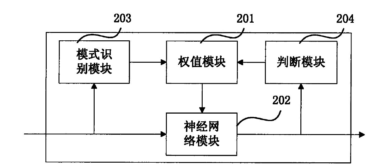
[0021] The following will clearly and completely describe the technical solutions in the embodiments of the present invention with reference to the accompanying drawings in the embodiments of the present invention. Obviously, the described embodiments are only some, not all, embodiments of the present invention. Based on the embodiments of the present invention, all other embodiments obtained by persons of ordinary skill in the art without making creative efforts belong to the protection scope of the present invention.

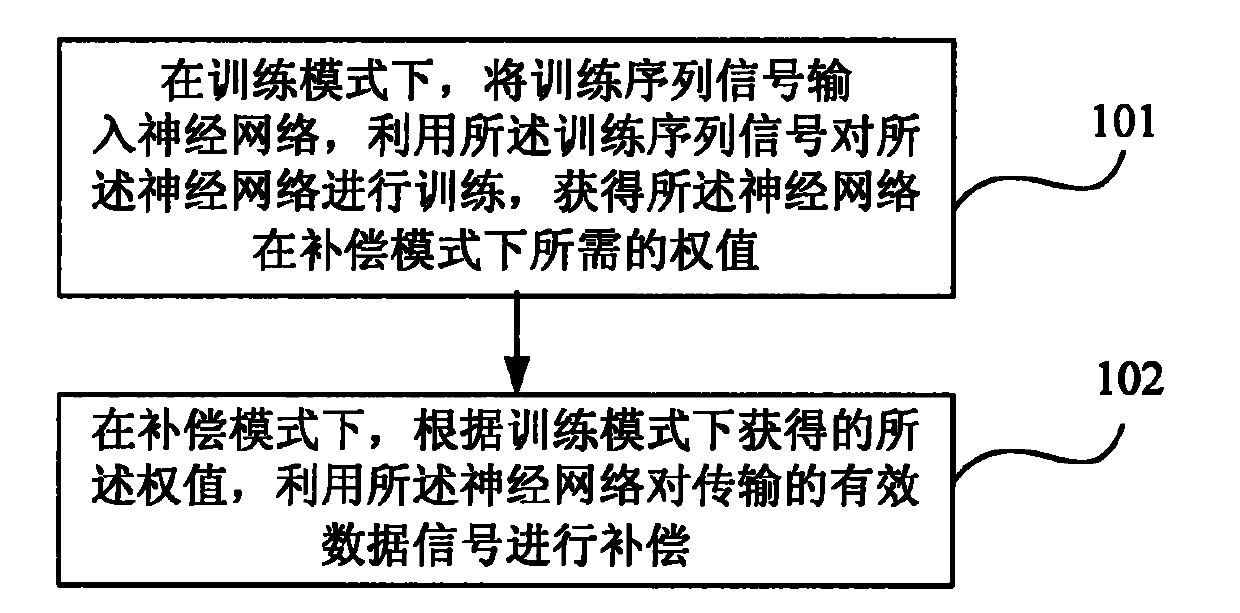
[0022] An embodiment of the present invention provides a method for signal damage compensation, the flow chart of which is as follows figure 1 As shown, the method includes:

[0023] 101. In the training mode, input a training sequence signal into the neural network, use the training sequence signal to train the neural network, and obtain weights required by the neural network in the compensation mode;

[0024] 102. In the compensation mode, use the neural ne...


PUM


Abstract

The embodiment of the invention provides a signal impairment compensation method, a signal impairment compensation device and an optical receiver. The method comprises the following steps of: in a training mode, inputting a training sequence signal into a neural network and training the neural network by using the training sequence signal so as to acquire a weight needed by the neural network in the compensation mode; and in the compensation mode, compensating a transmitted effective data signal by using the neural network according to the weight acquired in the training mode. In embodiment of the invention, signal impairment compensation can be performed without the changing of a network structure, a scheme structure is simple, and adaptive capability is achieved.

Description

technical field [0001] The invention relates to the communication field, in particular to a signal damage compensation method, device and optical receiver. Background technique [0002] With the popularity of high-speed Internet and the vigorous development of multimedia services, people have higher requirements for the bandwidth and transmission rate of Ethernet. From the initial 2.5G to 10G, and then from 10G to 40G. At present, the 10G system is still the mainstream transmission rate standard, but the coexistence of 40G and 10G, and the trend of replacing 10G is irreversible. 40G has already started commercial use in many countries and regions. However, people's requirements for bandwidth can be said to be endless, and the research on 100G has become a hot spot at present. Many people in the industry believe that 100G will achieve considerable development and commercialization in the next five years. The carrier of these high-speed communications can only be optical fi...

Claims


Application Information

Patent Timeline
Patent Type & Authority Applications(China)
IPC IPC(8): H04B10/18H04B10/2507
Inventor 张亮刘琦苏翼凯熊前进
Owner HUAWEI TECH CO LTD
Learn More