A lens adapter ring

A transfer and lens technology, applied in the field of photographic equipment, can solve problems such as top deformation, top breaking, lens top flower, etc., and achieve the effect of balanced force, convenient screwing operation, and safe operation.

Active Publication Date: 2019-01-18
ZHUHAI CHUANFU OPTICAL TECH
View PDF9 Cites 0 Cited by
  • Summary
  • Abstract
  • Description
  • Claims
  • Application Information

AI Technical Summary

Problems solved by technology

[0003] In order to solve the above-mentioned technical problems existing in the prior art, the present invention provides a force point on the inner surface of the front end of the lens is an annular surface, which has a good fixing effect and balanced force on the lens, which effectively solves the problem of fixing the traditional adapter circle point. The method causes the technical problems of lens top flower, top deformation and bursting, and also avoids touching the lens lens. It is a convenient, fast and safe lens adapter ring

Method used


Image

  • A lens adapter ring
  • A lens adapter ring
  • A lens adapter ring

Examples


Embodiment 1 2

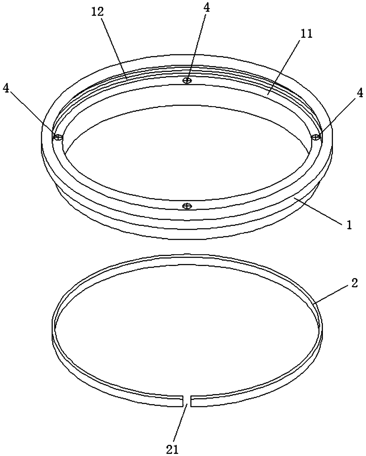
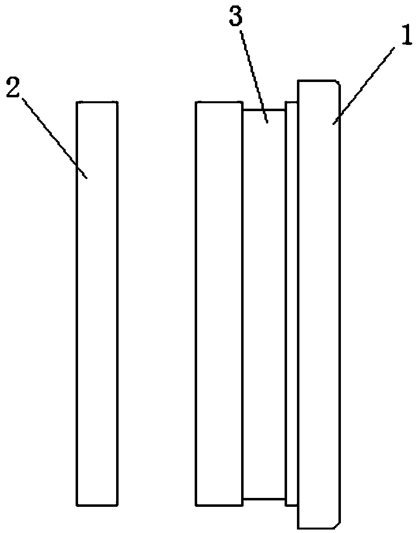
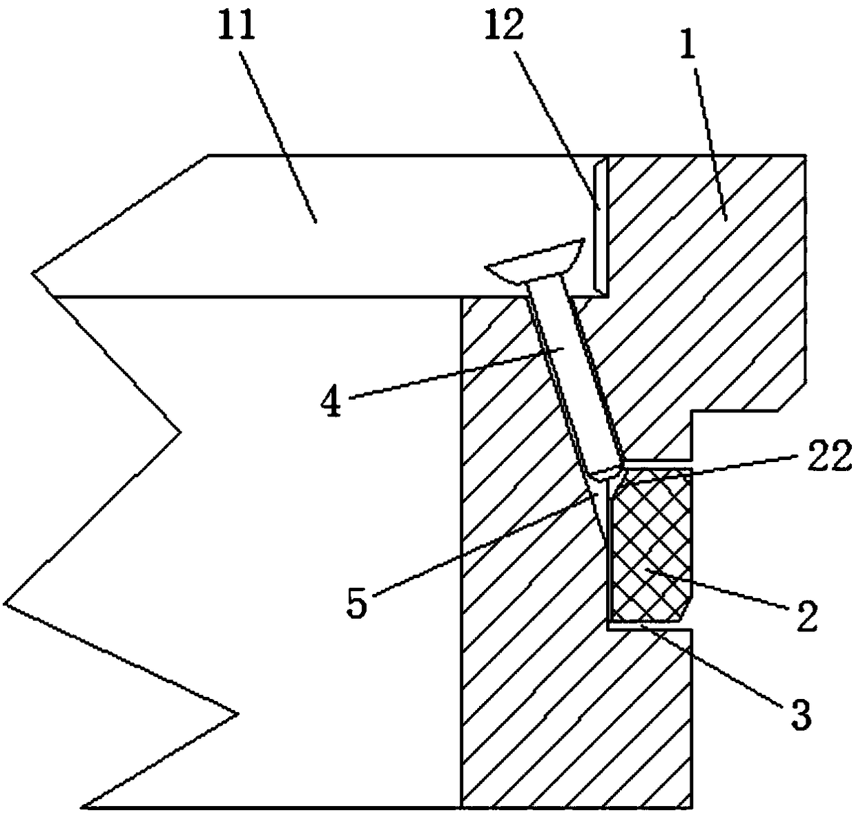
[0027] Such as Figure 1 to Figure 5 As shown in , Embodiments 1 and 2 of the present invention provide a lens adapter ring, including an adapter ring main body 1 and an external expansion fixing ring 2; wherein, the circumferential outer surface of the adapter ring main body 1 is provided with An annular groove 3, and the front end of the main body 1 of the adapter ring is provided with an external expansion drive mechanism; Under the action, it bulges outward and is higher than the peripheral outer surface of the main body 1 of the adapter ring. The specific structure can be as follows: the adapter ring main body 1 can be made of metal material or plastic material, and the external expansion fixing ring 2 can be a circular ring with a gap 21, and can be made of plastic material (of course , the expansion fixing ring 2 can also be a complete ring without a gap, and can also be made of silica gel material or elastic metal material.). The external expansion driving mechanism ...

Embodiment 3

[0032] Such as Figure 6 As shown in , Embodiment 3 of the present invention provides a lens adapter ring, the structure of which is basically the same as Embodiment 1 and Embodiment 2, including an adapter ring main body 1 and an external expansion fixing ring 2; wherein, the adapter ring The circumferential outer surface of the main body 1 is provided with an annular groove 3, and the front end of the adapter ring main body 1 is provided with an external expansion drive mechanism, and the external expansion drive mechanism includes more than two external expansion screws 4 and arranged in a ring array. There are more than two screw holes 5 at the front end of the main body 1 of the adapter ring. The expansion fixing ring 2 is arranged in the annular groove 3, and is connected with the drive mechanism of the expansion, and outwardly under the action of the drive mechanism of the expansion. Swell and be higher than the circumferential outer surface of the main body 1 of the ad...


PUM


Abstract

The invention relates to a lens adapter ring, which includes an adapter ring main body and an external expansion fixing ring; wherein, the circumferential outer surface of the adapter ring main body is provided with an annular groove, and the front end of the adapter ring main body is provided with External expansion drive mechanism; the external expansion fixing ring is set in the annular groove, and is connected with the external expansion drive mechanism in transmission, and under the action of the external expansion drive mechanism, it expands outward and is higher than the circumference of the main body of the adapter ring The outer surface. In this way, the stress point of the lens adapter ring acting on the inner surface of the front end of the lens is an annular surface, the fixing effect is good, and the force on the lens is balanced. No broken technical problems, the operation is very convenient and fast, and it also avoids touching the lens lens, making the operation safer.

Description

technical field [0001] The invention belongs to the technical field of photographic equipment, in particular to a lens adapter ring. Background technique [0002] At present, some lenses on the market do not have a thread structure on the front end (such as a cannon lens), so an adapter ring must be used when installing a filter. The existing adapter ring includes an adapter ring main body, and the inner surface of the adapter ring main body is provided with a fixing screw vertically passing through the adapter ring main body; since the fixing screw is very close to the lens, the operation is very difficult, inconvenient, and easy The lens is dirty and scratched, and the fixing effect is not ideal. When it is screwed in insufficiently, it is easy to loosen. When it is fully screwed in, the fixing screw often crumbles, deforms, and even breaks the inner surface of the front of the lens, causing damage to the lens. . Contents of the invention [0003] In order to solve the...

Claims


Application Information

Patent Timeline
Patent Type & Authority Patents(China)
IPC IPC(8): G03B17/14
CPCG03B17/14
Inventor 袁国奎
Owner ZHUHAI CHUANFU OPTICAL TECH
Why Eureka
Try Eureka