
Near field wireless communication antenna and portable terminal

A portable terminal and wireless communication technology, applied in the field of short-range wireless communication antennas and portable terminals, can solve the problem of not being able to maximize the efficiency of wireless communication, and achieve the goal of improving wireless communication efficiency, improving efficiency, and expanding communication distance and communication range. Effect

Inactive Publication Date: 2016-08-17
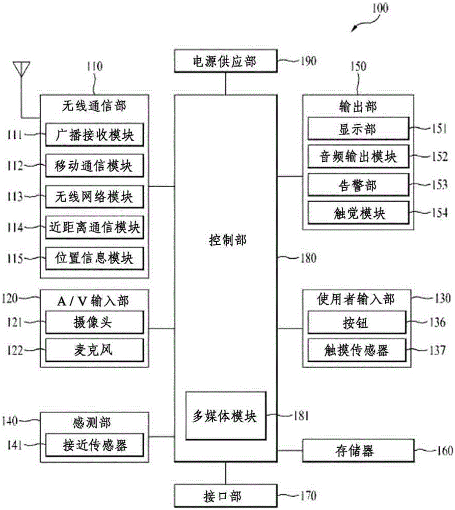
IMT INC
View PDF2 Cites 3 Cited by
  • Summary
  • Abstract
  • Description
  • Claims
  • Application Information

AI Technical Summary

Problems solved by technology

[0080] However, in the antenna device and the mobile communication terminal of prior art document 2, the efficiency of wireless communication cannot be maximized because the coil pattern 15 and the radiating part 20 simply overlap.

Method used


Image

  • Near field wireless communication antenna and portable terminal
  • Near field wireless communication antenna and portable terminal
  • Near field wireless communication antenna and portable terminal

Examples


Embodiment Construction

[0136] Next, preferred embodiments of the short-range wireless communication antenna and portable terminal of the present invention will be described in conjunction with the accompanying drawings. There may be multiple embodiments above, and the purpose, features and advantages of the present invention can be better understood through these embodiments.

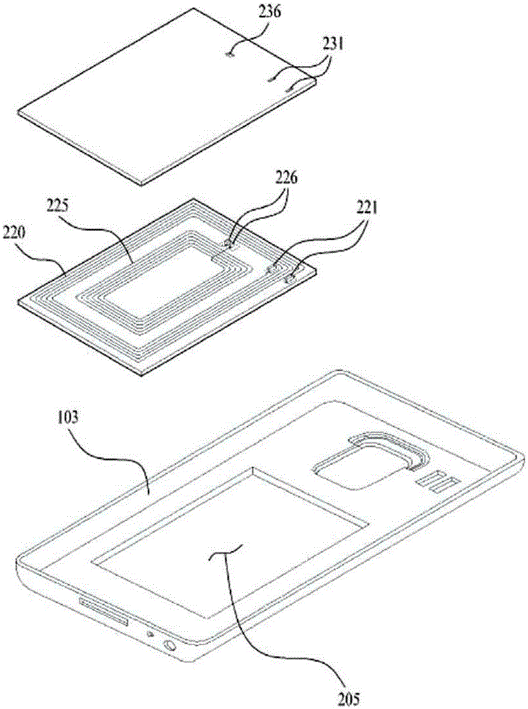
[0137] Figure 3a It is an exploded perspective view including a reader for explaining the short-range wireless communication antenna of the first embodiment of the present invention; Figure 3b is a plan view showing the short-range wireless communication antenna of the first embodiment of the present invention; Figure 4a It is an exploded perspective view including a reader for explaining the short-range wireless communication antenna of the second embodiment of the present invention; Figure 4b is a plan view showing a short-range wireless communication antenna according to a second embodiment of the present invention; ...


PUM


Abstract

The present invention relates to a near field wireless communication antenna and a portable terminal. A loop pattern (22) is patterned on a flexible film (21) from a start terminal (23) to an end terminal (24) while being connected to an adjacent metal plate (10) through a jump contact point (25) so that, resultantly, the flow of a signal current passes through the start terminal (23) and the jump contact point (25) to extend to the metal plate (10) and then again through the jump contact point (25) to extend to the end terminal (24), thus providing an expanding effect of the loop pattern (22) in which signal power is maximized to enable emission and allowing wireless communication efficiency to be more significantly improved.

Description

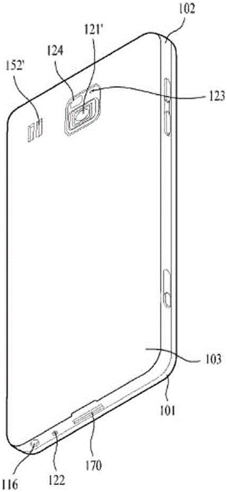
technical field [0001] The present invention relates to a short-range wireless communication antenna and a portable terminal, and more particularly, to a short-range wireless communication antenna and a portable terminal that maximize wireless communication efficiency. Background technique [0002] Generally speaking, a portable terminal is a smart terminal that adds computer-supported functions such as network communication and information search to a mobile phone. An example of this is a smartphone that uses the Internet and various applications (apps) through a window that can be viewed on the display screen. , NFC for short-range wireless communication is provided in such a portable terminal. [0003] As prior art document 1, Korean Laid-Open Patent No. 2013-0113222 (Antenna and Mobile Terminal Equipped with the Antenna) can be introduced. [0004] Figure 1a It is a block diagram of a mobile terminal related to prior art document 1. [0005] Such as Figure 1a As show...

Claims


Application Information

Patent Timeline
Patent Type & Authority Applications(China)
IPC IPC(8): H01Q1/22
CPCG06K19/077H01Q1/22H01Q1/24H01Q7/00G06K19/07773G06K19/07779H01Q1/2225H01Q1/243
Inventor 朴钟振朴正昵郑彰佑金敃炫
Owner IMT INC
Learn More