Terminal antenna and intelligent terminal

A technology of terminal antenna and intelligent terminal, which is applied in the field of communication

Inactive Publication Date: 2016-08-17
GUANGDONG OPPO MOBILE TELECOMM CORP LTD
View PDF16 Cites 33 Cited by
  • Summary
  • Abstract
  • Description
  • Claims
  • Application Information

AI Technical Summary

Problems solved by technology

However, this layout will bring some changes to the design of the whole machine. For example, the display drive circuit needs to be set at the top of the display screen, and the headphone jack needs to be set at one end of the terminal’s Home button. These changes will affect the application environment of the antenna. wait for new changes

Method used


Image

  • Terminal antenna and intelligent terminal
  • Terminal antenna and intelligent terminal
  • Terminal antenna and intelligent terminal

Examples


Embodiment 1

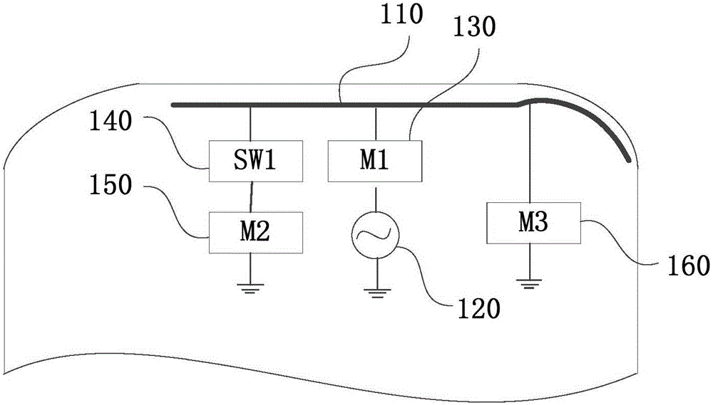
[0020] figure 1 It is a structural diagram of a terminal antenna in Embodiment 1 of the present invention, refer to figure 1 , the terminal antenna includes: a first antenna 110 , a first feed 120 , a first matching circuit 130 , a first switch 140 , a second matching circuit 150 and a third matching circuit 160 . Wherein, the first port of the first antenna 110 is connected to the first feed 120 through the first matching circuit 130 , and the first matching circuit 130 is used for matching the first antenna 110 . The second matching circuit 150 includes multiple matching paths for spreading the high-frequency band of the first antenna 110. The second port of the first antenna 110 passes through the multiple matching paths of the first switch 140 and the second matching circuit 150. connect. The third port of the first antenna 110 is connected to the third matching circuit 160 , and the third matching circuit 160 is used for spreading the low frequency band of the first ant...

Embodiment 2

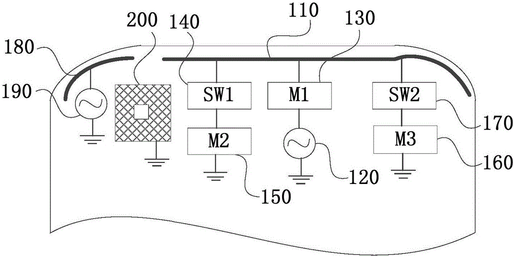
[0025] This embodiment provides a terminal antenna on the basis of the foregoing embodiments. figure 2 is a structural diagram of a terminal antenna in Embodiment 2 of the present invention. It should be noted that, for the convenience of expression, in this embodiment figure 2 And the accompanying drawings in the following embodiments still use the first embodiment figure 1 reference signs. Such as figure 2 As shown, different from the above-mentioned embodiments, in this embodiment, the terminal antenna further includes: a second switch 170, the third matching circuit 160 includes multiple matching paths, and the third port of the first antenna 110 passes through the second switch 170 It is connected to multiple matching paths of the third matching circuit 160 .

[0026] Wherein, the second switch 170 is a single-pole multi-throw switch, by switching the second switch 170, it can switch to multiple matching paths of the third matching circuit 160, so as to realize the ...

Embodiment 3

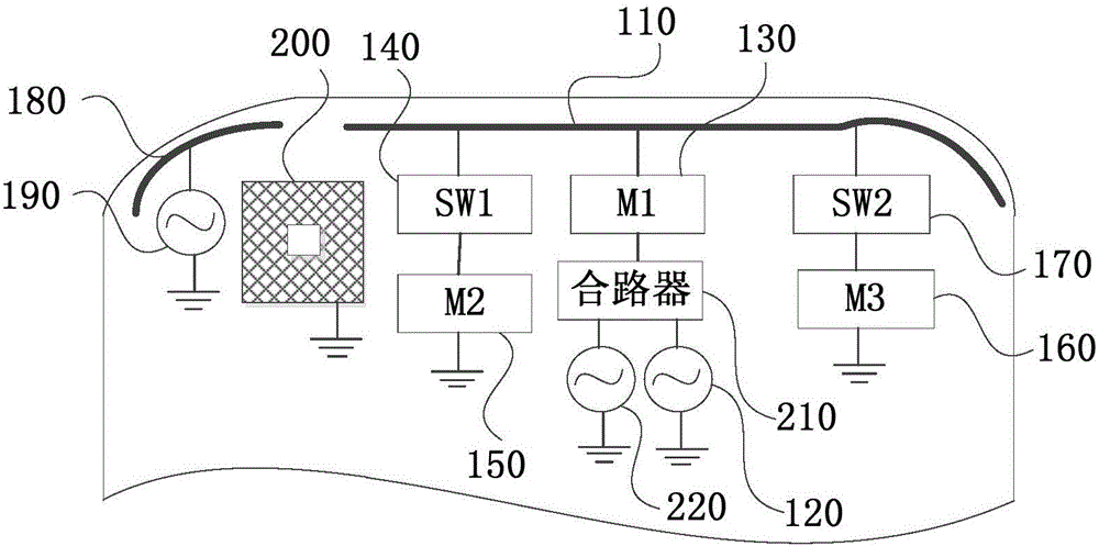
[0033] This embodiment provides a terminal antenna on the basis of the foregoing embodiments. image 3 It is a structural diagram of a terminal antenna in Embodiment 3 of the present invention. Such as image 3 As shown, different from the above embodiment, in this embodiment, the terminal antenna further includes: a combiner 210 and a third feed 220, wherein the first end of the combiner 210 is connected to the first matching circuit 130, The second end is connected to the first feed source 120 , and the third end is connected to the third feed source 220 .

[0034] Wherein, the combiner 210 is configured to filter the transmission signals of the first feed source 120 and the third feed source 220 , and respectively feed the transmission signals of the first feed source 120 and the third feed source 220 to the first antenna 110 . Optionally, the first feed 120 is a diversity antenna feed, the second feed 190 is a wireless network antenna feed, and the third feed 220 is a glob...


PUM


Abstract

An embodiment of the invention discloses a terminal antenna and an intelligent terminal. The terminal antenna comprises a first antenna, a first feed source, a first matching circuit, a first switch, a second matching circuit and a third matching circuit, wherein a first port of the first antenna is connected with the first feed source through the first matching circuit; the first matching circuit is used for matching the first antenna; the second matching circuit comprises a plurality of matching channels and is used for spreading a spectrum of a high frequency band of the first antenna; a second port of the first antenna is connected with the plurality of matching channels of the second matching circuit through the first switch; a third port of the first antenna is connected with a third matching circuit; the third matching circuit is used for spreading a spectrum of a low frequency band of the first antenna. With adoption of the scheme of the embodiment, overall space of the terminal is reasonably used, and multi-frequency band and large bandwidth of the antenna in the terminal are realized.

Description

technical field [0001] Embodiments of the present invention relate to communication technologies, and in particular to a terminal antenna and an intelligent terminal. Background technique [0002] With the continuous development of science and technology, smart terminals such as mobile phones have become one of the indispensable tools for daily use due to their rich functions and strong display effects. [0003] At present, fingerprint functions such as fingerprint unlocking and fingerprint payment have gradually become common functions of smart terminals. In some mobile phones, the fingerprint identification module is set on the front of the mobile phone and integrated with the Home button to improve user experience. However, this layout will bring some changes to the design of the whole machine. For example, the display drive circuit needs to be set at the top of the display screen, and the headphone jack needs to be set at one end of the terminal’s Home button. These cha...

Claims


Application Information

Patent Timeline
Patent Type & Authority Applications(China)
IPC IPC(8): H01Q5/50H01Q5/328H01Q5/20H01Q5/335H01Q21/30H01Q1/24
CPCH01Q5/50H01Q1/243H01Q5/20H01Q5/328H01Q5/335H01Q21/30
Inventor 吴青
Owner GUANGDONG OPPO MOBILE TELECOMM CORP LTD
Why Eureka
Try Eureka