Antenna assembly for wireless device

a wireless device and antenna assembly technology, applied in the direction of individual energised antenna arrays, antenna earthings, separate antenna unit combinations, etc., can solve the problems of limited bandwidth, large size, interference from other nearby objects, etc., and achieve high frequency bandwidth, high frequency bandwidth, high frequency bandwidth

Active Publication Date: 2019-09-10
TYCO ELECTRONICS LOGISTICS AG (CH)
View PDF28 Cites 2 Cited by
  • Summary
  • Abstract
  • Description
  • Claims
  • Application Information

AI Technical Summary

Benefits of technology

[0008]In one embodiment, an antenna assembly for a wireless device is provided including an antenna cable having a feed line and a ground shield coaxial with the feed line and a substrate having a feed line mounting pad and a ground shield mounting pad. The antenna includes a low band ground terminal, a low band feed terminal, a high band ground terminal and a high band feed terminal. The low band ground terminal is on the substrate and operable in a low frequency bandwidth. The low band ground terminal is electrically coupled to the ground shield of the antenna cable and capacitively coupled to the feed line of the antenna cable. The low band feed terminal is operable in a low frequency bandwidth and electrically coupled to the feed line of the antenna cable. The high band ground terminal is operable in a high frequency bandwidth. The high band ground terminal is electrically coupled to the ground shield of the antenna cable and capacitively coupled to the feed line of the antenna cable. The high band feed terminal is operable in a high frequency bandwidth and electrically coupled to the feed line of the antenna cable. The low band ground terminal and the high band ground terminal are ground plane independent. The antenna includes a tuning element on the substrate being operatively coupled to at least one of the low band ground terminal, the low band feed terminal, the high band ground terminal and the high band feed terminal.

Problems solved by technology

Known antennas for wireless devices have several disadvantages, such as limited bandwidth, large size, interference from other nearby objects, and the like.
Such antennas have expanded bandwidth to cover broader frequency ranges, but still run into bandwidth limitations.
Known antennas for wireless devices are not able to effectively address these needs, at least in part due to bandwidth limitations.

Method used


Image

  • Antenna assembly for wireless device
  • Antenna assembly for wireless device
  • Antenna assembly for wireless device

Examples


Embodiment Construction

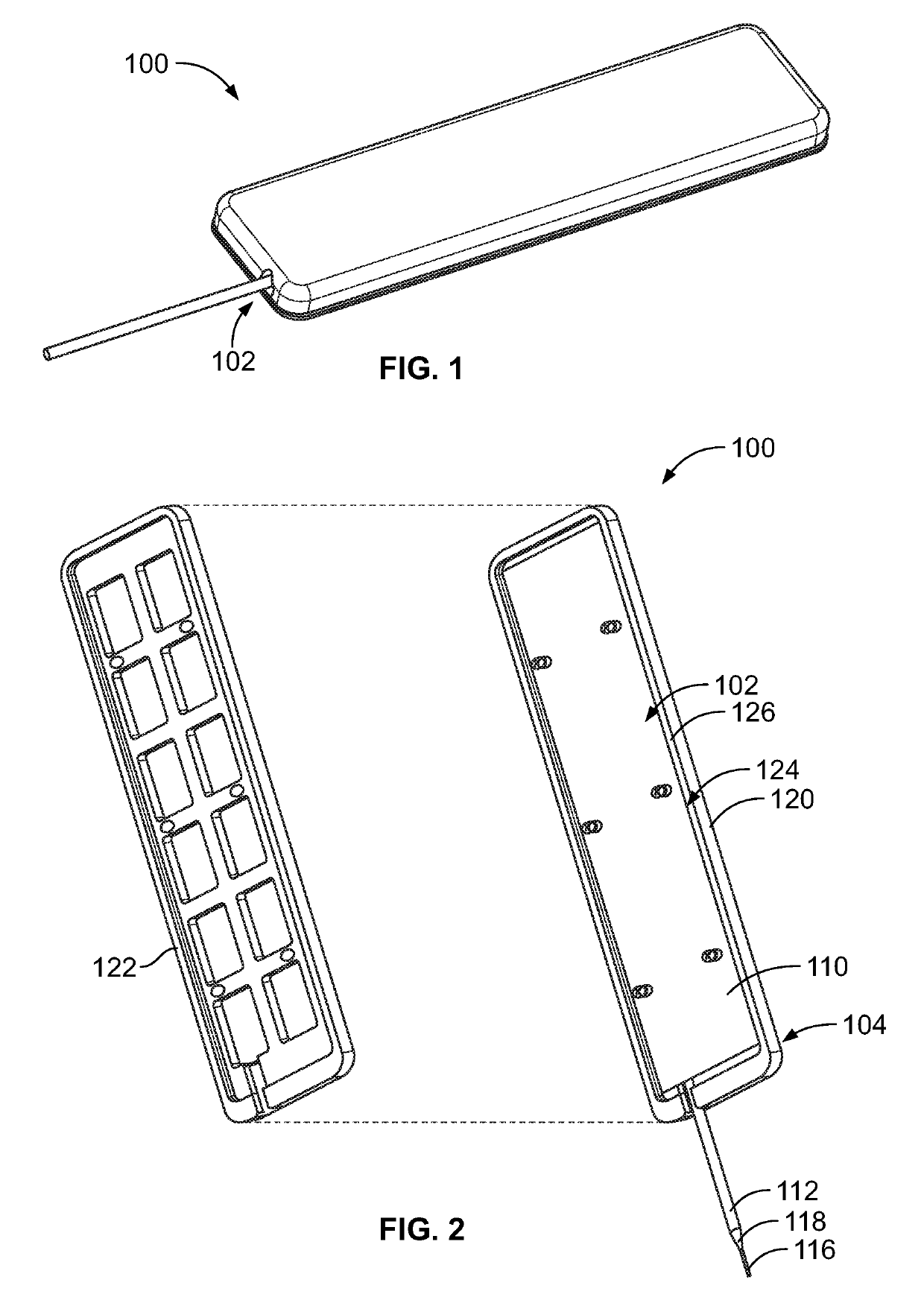
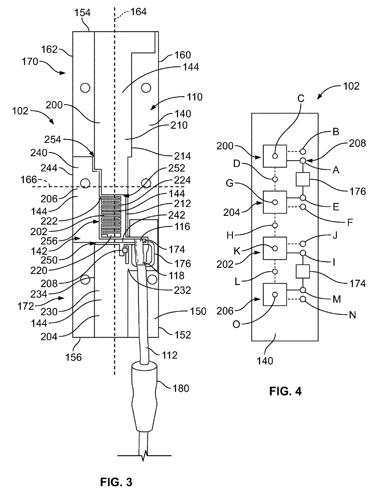
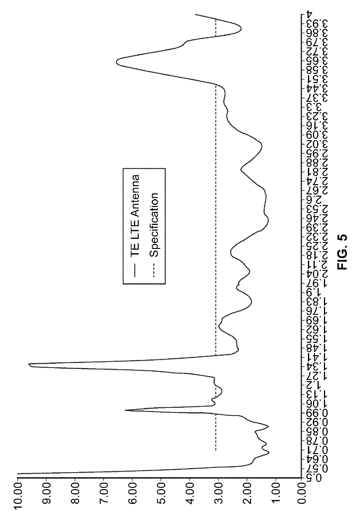
[0014]Embodiments set forth herein include an antenna assembly having an antenna electrically connected to an antenna cable. Various embodiments of the antenna described herein include a multi-band antenna circuit. For example, various embodiments described herein include an antenna circuit operable in a low frequency band and a high frequency band. Various embodiments may include a dual dipole antenna circuit. The dual dipole antenna circuit may be operable in different frequency bands, such as in different Wi-Fi frequency bands. For example, in various embodiments described herein include an antenna circuit operable within frequency ranges of 698 to 960 MHz, 1.4 to 3.5 GHz and 3.8 to 4 GHz, which provides frequency coverage and enables use in many discrete worldwide cellular bands. The antenna circuit may be operable in other frequency ranges in other various embodiments. The antenna element may have a wide bandwidth. Various embodiments described herein have an antenna arranged f...


PUM


Abstract

An antenna assembly for a wireless device includes an antenna cable having a feed line and a ground shield and a substrate. The antenna includes a low band ground terminal, a low band feed terminal, a high band ground terminal and a high band feed terminal. The low band ground terminal is electrically coupled to the ground shield of the antenna cable and capacitively coupled to the feed line of the antenna cable. The low band feed terminal is electrically coupled to the feed line of the antenna cable. The high band ground terminal is electrically coupled to the ground shield of the antenna cable and capacitively coupled to the feed line of the antenna cable. The high band feed terminal is electrically coupled to the feed line of the antenna cable. The low band ground terminal and the high band ground terminal are ground plane independent.

Description

BACKGROUND OF THE INVENTION[0001]The subject matter herein relates generally to antenna assemblies for wireless devices.[0002]Wireless devices or wireless communication devices have use in many applications including telecommunications, computers, vehicles and other applications. Examples of wireless devices include mobile phones, cellular modems, tablets, notebook computers, laptop computers, desktop computers, handsets, personal digital assistants (PDAs), a wireless access point (AP) such as a WiFi router, a base station in a wireless network, a wireless communication USB dongle or card (e.g., PCI Express card or PCMCIA card) for computers, and other devices. The wireless devices include antennas that allow for wireless communication with the device. Several antenna characteristics are usually considered in selecting an antenna for a wireless device, including the size, voltage standing wave ratio (VSWR), gain, bandwidth, and the radiation pattern of the antenna.[0003]Known antenn...

Claims


Application Information

Patent Timeline
Patent Type & Authority Patents(United States)
IPC IPC(8): H01Q1/24H01Q1/48H01Q21/30H01Q21/06
CPCH01Q1/243H01Q1/48H01Q21/30H01Q21/062H01Q5/314H01Q9/065H01Q15/0086H01Q23/00
Inventor YUN, XINGBISHOP, BRUCE FOSTERHALL, JOHN WESLEYSCHROLL, NEIL FRANKLIN
Owner TYCO ELECTRONICS LOGISTICS AG (CH)
Why Eureka
Try Eureka