
Antenna system and mobile terminal

An antenna system and antenna radiation technology, applied in the directions of antennas, antenna parts, antenna grounding devices, etc., can solve the problems of increased cost and the inability of the antenna system to be recycled and reused.

Active Publication Date: 2018-07-27
AAC TECH PTE LTD
View PDF11 Cites 2 Cited by
  • Summary
  • Abstract
  • Description
  • Claims
  • Application Information

AI Technical Summary

Problems solved by technology

[0003] However, the inventors of the present invention found that since 5G is not popularized at present, the antenna systems in existing mobile terminals such as mobile phones can only work in 2G, 3G, and 4G frequency bands. If they want to support 5G frequency bands, they need to be newly prepared Replacing the antenna system for the 5G frequency band, the existing antenna system cannot be recycled and reused, which will undoubtedly increase the cost

Method used


Image

  • Antenna system and mobile terminal
  • Antenna system and mobile terminal
  • Antenna system and mobile terminal

Examples


Embodiment Construction

[0020] In order to make the object, technical solution and advantages of the present invention clearer, various embodiments of the present invention will be described in detail below in conjunction with the accompanying drawings. However, those of ordinary skill in the art can understand that in each implementation manner of the present invention, many technical details are proposed in order to enable readers to better understand the present invention. However, even without these technical details and various changes and modifications based on the following implementation modes, the technical solution claimed in the present invention can also be realized.

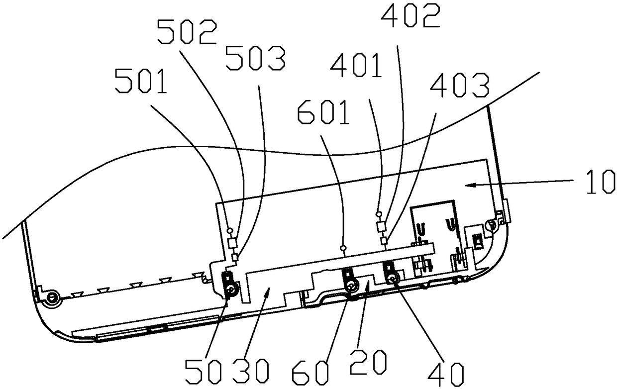
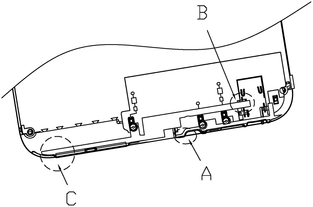
[0021] A first embodiment of the invention relates to an antenna system. Such as figure 1 As shown, the antenna system includes a circuit board 10, a first antenna radiating part 20 and a second antenna radiating part 30, and a feeding point 601, a first grounding point 401, a second grounding point 501, The first radio f...


PUM


Abstract

The invention relates to the field of communication, and discloses an antenna system and a mobile terminal. The antenna system comprises a first antenna radiation part, a second antenna radiation partand a circuit board, wherein the circuit board is provided with a first radio frequency switch, a second radio frequency switch, a first matching circuit, a second matching circuit, a feeding point,a first grounding point and a second grounding point, the feeding point is electrically connected with the first antenna radiation part so as to achieve feeding of the first antenna radiation part, one end of the first radio frequency switch is electrically connected to the first grounding point, the other end of the first radio frequency switch is connected to the first antenna radiation part byconnecting the first matching circuit so as to achieve grounding of the first antenna radiation part, one end of the second radio frequency switch is electrically connected to the second grounding point, the other end of the second radio frequency switch is connected to the second antenna radiation part by connecting the second matching circuit so as to achieve grounding of the second antenna radiation part, and the second antenna radiation part and the first antenna radiation part are arranged at intervals to achieve electromagnetic coupling. The antenna system and the mobile terminal, provided by the invention, have wide frequency band and high performance and are simultaneously low in implement cost.

Description

technical field [0001] The invention relates to the communication field, in particular to an antenna system and a mobile terminal. Background technique [0002] With the rapid development of communication technology, 5G network, as the fifth-generation mobile communication network, has a theoretical maximum transmission speed of tens of Gb per second, which is hundreds of times faster than the transmission speed of 4G network. High-quality movies can be downloaded within 1 second. [0003] However, the inventors of the present invention have found that since 5G is not popularized at present, the antenna systems in existing mobile terminals such as mobile phones can only work in 2G, 3G, and 4G frequency bands. To replace the antenna system for the 5G frequency band, the existing antenna system cannot be recycled and reused, which will undoubtedly increase the cost. Contents of the invention [0004] The purpose of the embodiment of the present invention is to provide an a...

Claims


Application Information

Patent Timeline
Patent Type & Authority Applications(China)
IPC IPC(8): H01Q1/36H01Q1/48H01Q1/50H01Q1/24
CPCH01Q1/243H01Q1/36H01Q1/48H01Q1/50
Inventor 韩莉姜华
Owner AAC TECH PTE LTD
Learn More