Low-noise and wide-pressure audio-signal conditioning circuit based on self-calibration and dynamic gain adjustment

An audio signal and dynamic gain technology, applied in the field of audio analyzers, can solve the problems of signal amplitude adjustment, limited accuracy, influence of measurement accuracy, etc., to achieve the effect of eliminating errors and suppressing noise

Active Publication Date: 2016-08-17
THE 41ST INST OF CHINA ELECTRONICS TECH GRP
View PDF10 Cites 11 Cited by
  • Summary
  • Abstract
  • Description
  • Claims
  • Application Information

AI Technical Summary

Problems solved by technology

[0004] Differential input mode, precision resistor network and shielding are relatively traditional technologies, which have limited effect on improving the indicators of audio analyzers; fixed gain adjustment technology, in order to adjust the signal with larger amplitude to the acquisition range suitable for AD, the gain adjustment is generally Set it to a larger attenuation range; when measuring a small signal, the amplitude of the small signal reaching the AD end after gain adjustment will be very small, and the measurement accuracy will be affected; the fixed gain adjustment is divided into two levels, although the above problems can be avoided, but Its gain adjustment options are less, it is difficult to adjust the signal amplitude to the most accurate range of AD sampling, and the accuracy is still limited

Method used


Image

  • Low-noise and wide-pressure audio-signal conditioning circuit based on self-calibration and dynamic gain adjustment
  • Low-noise and wide-pressure audio-signal conditioning circuit based on self-calibration and dynamic gain adjustment
  • Low-noise and wide-pressure audio-signal conditioning circuit based on self-calibration and dynamic gain adjustment

Examples


Embodiment Construction

[0027] The present invention will be further described below in conjunction with the accompanying drawings and embodiments.

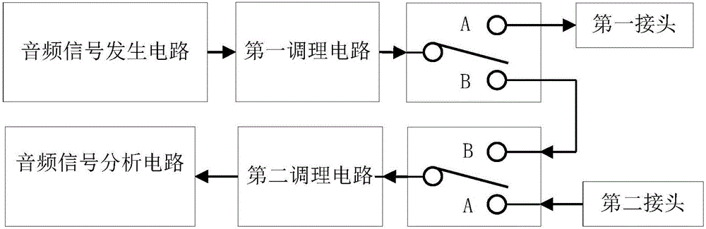
[0028] Such as figure 1 As shown, the low-noise wide-voltage audio signal conditioning circuit based on self-calibration and dynamic gain adjustment includes an audio signal analysis channel and an audio signal generation channel. There are two audio signal analysis channels and two audio signal generation channels. Through the internal switch setting, control the connection or disconnection of the audio signal generation channel and the audio signal analysis channel, such as figure 1 Shown is the self-calibration technology channel intent.

[0029] The audio signal generation channel includes an audio signal generation circuit, a first conditioning circuit, and a first one-of-two switch, and the audio signal analysis channel includes an audio signal analysis circuit, a second conditioning circuit, and a second one-of-two switch;

[0030] The audio si...


PUM


Abstract

The invention discloses a low-noise and wide-pressure audio-signal conditioning circuit based on self-calibration and dynamic gain adjustment. The low-noise wide-pressure audio-signal conditioning circuit comprises an audio-signal analysis channel and an audio-signal generation channel, and connection or disconnection of the audio-signal analysis channel and connection or disconnection of the audio-signal generation channel are achieved by setting a multiple-or switch; an audio-signal analysis circuit in the audio-signal analysis channel comprises a multistage gain control circuit, signals with the large amplitude are attenuated step by step, signals with the small amplitude are amplified step by step till the signal amplitude is adjusted to the set size within the range of ADC sampling. According to the audio-signal self-calibration technology, audio signals are generated through an audio analyzer and collected by the audio-signal analysis channel to be turned to audio analyzer software to form closed-loop calibration, errors of the audio-signal analysis channel can be thoroughly eliminated, and noise is inhibited; the effect of low-noise wide-pressure audio-signal conditioning circuit based on self-calibration and dynamic gain adjustment is better than the traditional differential input technology, the traditional precision resistance network technology, the traditional shielding technology and the like in noise inhibiting aspect.

Description

technical field [0001] The invention relates to the technical field of audio analyzers, in particular to a low-noise wide-voltage audio signal conditioning circuit based on self-calibration and dynamic gain adjustment. Background technique [0002] Audio analyzers are widely used in military and civilian fields, and can provide audio frequency response, total harmonic distortion, etc. tests for military radio stations, submarine sonar and other equipment; while military equipment outputs audio signals in a wide range of voltages during testing, ranging from A few millivolts to tens of volts; in order to meet the test requirements, the input channel of the audio analyzer needs to have a large dynamic range; and when measuring small signals, the noise of the input channel has a great impact on the measurement results, which is the biggest way to improve the measurement accuracy obstacle. Therefore, the design of low noise and wide voltage range input signal conditioning circu...

Claims


Application Information

Patent Timeline
Patent Type & Authority Applications(China)
IPC IPC(8): H03G3/30
CPCH03G3/3026H03G2201/504
Inventor 薛沛祥宋志刚王建中唐丽萍缪国锋陈庆磊
Owner THE 41ST INST OF CHINA ELECTRONICS TECH GRP
Why Eureka
Try Eureka