Audio signal squeaking detection method

An audio signal and detection method technology, applied in the direction of transducer acoustic response prevention, electrical components, etc., can solve the problems of easy misjudgment, slow response speed, low accuracy rate, etc., achieve low customer service accuracy rate and reduce misjudgment Effect

Inactive Publication Date: 2016-08-17
成都普创通信技术股份有限公司
View PDF3 Cites 19 Cited by
  • Summary
  • Abstract
  • Description
  • Claims
  • Application Information

AI Technical Summary

Problems solved by technology

[0003] The technical problem to be solved by the present invention is to accurately detect whether there i

Method used


Image

  • Audio signal squeaking detection method

Examples


Embodiment 1

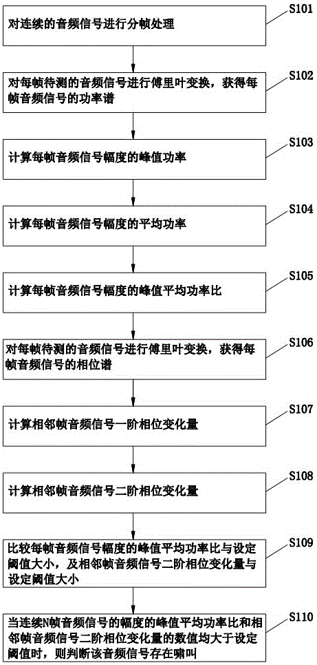
[0028] Such as figure 1 as shown, figure 1 It is a flow chart of the audio signal howling detection method provided by Embodiment 1 of the present invention.

[0029] In this embodiment, the audio signal howling detection method specifically includes:

[0030] S101. Perform frame division processing on continuous audio signals.

[0031] The audio signal cannot be directly processed as a quasi-stationary signal. In this embodiment, before the signal processing, the continuous audio signal is divided into frames, and the length of each frame is about 20-30ms. for further processing.

[0032] S102. Perform Fourier transform on each frame of the audio signal to be tested to obtain a power spectrum of each frame of the audio signal.

[0033] The power spectrum is the abbreviation of the power spectral density function, which is defined as the signal power in the unit frequency band. It represents the variation of signal power with frequency, that is, the distribution of signal...


PUM


Abstract

The invention discloses a howling detection method of an audio signal. By calculating the peak-to-average power ratio of the amplitude of the audio signal and the second-order phase change of the audio signal of adjacent frames, and comparing the calculation result with a preset threshold, it can Accurately detect whether there is howling during audio signal transmission, reduce misjudgment, and solve the problems of low accuracy and prone to misjudgment of traditional detection methods.

Description

technical field [0001] The invention relates to the technical field of audio transmission systems, in particular to an audio signal howling detection method. Background technique [0002] With the rapid development of communication technology, people's requirements for communication quality are getting higher and higher. In the process of audio transmission, part of the sound emitted from the speaker of the audio system may leak back to the speaker. At this time, the amplification and feedback of the system Appear at the same time, forming a positive feedback phenomenon, resulting in howling. The existence of howling greatly reduces the communication quality. In order to eliminate howling, thereby improving communication quality and user experience, it is very important to detect howling in real time during voice transmission. The traditional howling detection method is based on the audio signal amplitude as the judgment condition. When the amplitude peak value of a certai...

Claims


Application Information

Patent Timeline
IPC IPC(8): H04R3/02
CPCH04R3/02H04R2420/05
Inventor 杜鹢刘刚杨俊
Owner 成都普创通信技术股份有限公司
Why Eureka
Try Eureka