Compactor system and method

A technology of compactor and compaction force, applied in the direction of presses, manufacturing tools, etc., can solve problems such as damage, equipment damage, personnel, manipulation and transportation difficulties.

Inactive Publication Date: 2016-08-17
TECH OIL PROD INC
View PDF8 Cites 2 Cited by
  • Summary
  • Abstract
  • Description
  • Claims
  • Application Information

AI Technical Summary

Problems solved by technology

The design is problematic because the weight of the carts makes maneuvering and transporting the carts up and down the slope into and out of the compaction unit difficult, especially in view of the rocking action (pitching and heaving) of seagoing vessels
Because of its weight and instability on the slope, the container experiences unintended motion and rolls down and off the slope, which can lead to equipment damage and personal injury

Method used


Image

  • Compactor system and method
  • Compactor system and method
  • Compactor system and method

Examples


Embodiment Construction

[0059] DETAILED DESCRIPTION OF THE PREFERRED EMBODIMENT

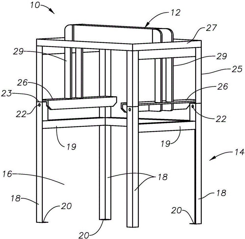
[0060] The compactor system may include a compaction unit having a frame assembly 10 such as image 3 and Figure 4 shown. The frame assembly 10 may include a movable upper frame portion 12 and a fixed lower frame portion 14 . The frame assembly 10 may also include a cavity 16 . The fixed lower frame portion 14 may include legs 18 interconnected by struts 19 in spaced relationship. Legs 18 may be configured in a square, rectangular, or other arrangement to form cavity 16 . The fixed lower frame part 14 supports the movable upper frame part 12 . A foot member 20 may be operably connected to a lower end of each of the legs 18 . Footing members 20 may be used to secure frame assembly 10 to a base structure to stabilize the compactor system when the ship is in motion. The base structure may be the base of a marine vessel such as a ship or an offshore installation.

[0061] The upper end of each leg 18 of the lower fr...


PUM


Abstract

A compactor system for use on board marine vessels and offshore installation. The compactor has a cart with bottom and side members capable of withstanding a compaction force. The upper rim of the cart has a lip. The system has a compaction unit formed of a movable upper frame with a shoulder and a lower fixed frame. During waste compaction, the moveable upper frame moves in an upward direction to a point where the shoulder engages the cart's lip to establish a force-distribution loop among the upper frame and the side and bottom members of the cart. The cart's wheels are not subjected to the compaction force.

Description

[0001] Cross References to Related Applications [0002] This application claims the benefit of and priority to US Provisional Application No. 61 / 882,952, filed September 26, 2013, which is incorporated herein by reference. field of invention [0003] The present invention relates to compactor systems and methods, and more particularly to waste compactor systems and methods for use on board marine vessels (eg, ships) and offshore installations. Background of the invention [0004] Environmental concerns over the world's navigable waterways have resulted in regulations governing waste treatment and disposal on board marine vessels (eg, steamships) and offshore installations. Regulations have generally changed over the past few years and will continue to change to provide stricter rules for waste disposal from ships at sea. International regulations include ISO 14001, IMO Marpol 73 / 78 Annex V and others. In the US, regulations include the MPRSA Marine Protected Research and ...

Claims


Application Information

Patent Timeline
Patent Type & Authority Applications(China)
IPC IPC(8): B30B9/30
CPCB30B9/3032B30B9/3042B30B9/3057B30B9/3075
Inventor 约翰·C·齐默
Owner TECH OIL PROD INC
Why Eureka
Try Eureka